


READ AND SAVE THESE INSTRUCTIONS
Model SP-B
Model CSP-B
Ceiling Exhaust and Inline Fans
PN 455480
Installation, Operation and Maintenance Manual
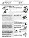
Prepare the Fan
1. If power assembly (motor and wheel) is not installed in housing, insert
the electrical plug into fan socket, then slide wheel end of power
assembly into fan housing and rotate clockwise until it is positioned
under tabs. Align the holes and attach by using two sheet metal
screws provided, shown in Fig. 1.
Ceiling Radiation Damper - CRD
1. If fan is to be used in a fire resistive membrane ceiling, a ceiling
radiation damper must be used. Otherwise proceede to Install the
Fan.
2. If the ceiling radiation damper is already mounted to the fan from the factory,
proceed to Install the Fan.
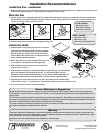
3. To mount the ceiling radiation damper to fan, make sure grille
attachment tabs are facing down. Then place the inlet part of the
fan into the ceiling radiation damper collar, and use self-tapping
sheet metal screws #10x
1
/2 in. (by
others) to screw through the damper
collar and into the fan housing, shown in
Fig. 2. If the fan/light combination is being
used, make sure ceiling radiation damper
has an electrical plug in it. The electrical
plug must be inserted into the fan. Make
sure the electrical wire will not interfere with
damper operation, shown in Fig. 3.
Wires from lighted grille
Wires to ceilin
g
fa
n
Do not allow
interference in
this area
Fig. 1
Fig. 3
Install the Fan
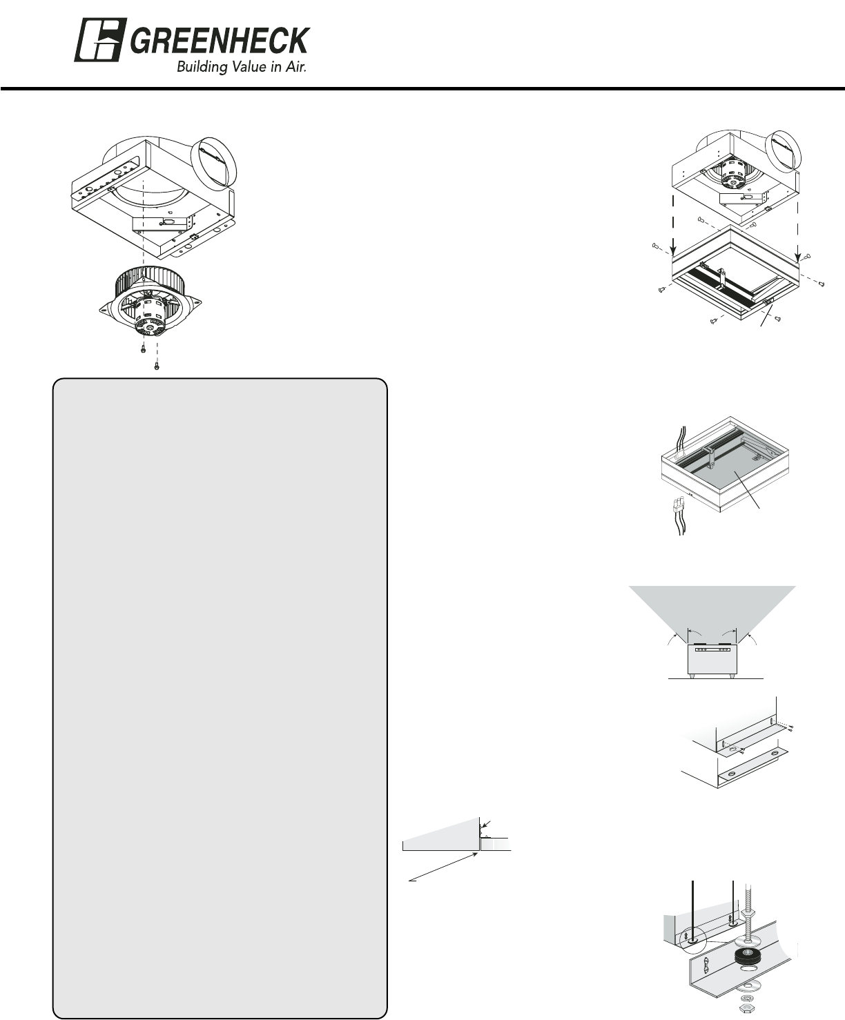
1. For best performance, choose a
location with the shortest possible duct
run and minimum number of elbows. Do
not mount near cooking equipment, shown
in Fig. 4.
2. Attach adjustable mounting brackets to
fan, but leave the screws loose until
proper height is determined, shown in
Fig. 5. For fan and fan/light combination
opening, cut a 14
1
⁄8 by 11
3
⁄4 inch hole in
the ceiling. For fan/CRD combination
opening, cut a 14
3
⁄8 by 12
1
⁄4 inch hole in the
ceiling.
For Frame Construction: Position unit
between joists. Position brackets such
that bottom edge of housing will be flush
with finished ceiling, and tighten the
adjustable
mounting brackets,
shown in Fig. 6.
For Hanging Installations: Use Greenheck’s
optional vibration isolator kit Part Number VI
Kit. Using the fan’s standard adjustable
mounting brackets and 10 by 32 threaded
rod (by others) hang unit as shown in Fig. 7.
Fig. 4
Do not install
fan in this area
45º
45º
Brackets can be
arranged to adapt
to most mounting
conditions
Fig. 5
Fig. 6
1. Adjust to be flush
with finished ceiling
Fan
Ceiling
2. Tighten
Fig. 7
®
WARNING !
To reduce the risk of fire, electric shock, or injury to
persons, observe the following:
• Suitable for use with solid-state speed controls.
• Use this unit only in the manner intended by the
manufacturer. If you have questions, contact the
manufacturer.
• Before servicing or cleaning unit, switch power off at
service panel and lock service disconnecting means to
prevent power from being switched on accidentally.
When the service disconnecting means cannot be
locked, securely fasten a prominent warning device,
such as a tag, to the service panel.
• Installation work and electrical wiring must be done by
qualified person(s) in accordance with all applicable
codes and standards, including fire-rated construction.
• Sufficient air is needed for proper combustion and
exhausting of gases through the flue (chimney) of fuel
burning equipment to prevent back drafting. Follow the
heating equipment manufacturer’s guideline and safety
standards such as those published by the National Fire
Protection Association (NFPA), and the American
Society for Heating, Refrigeration and Air Conditioning
Engineers (ASHRAE) and the local code authorities.
• When cutting or drilling into wall or ceiling, do not
damage electrical wiring or other hidden utilities.
• Acceptable for use over a bathtub or shower when
installed in a GFCI protected branch circuit. (Up
through size SP-A390)
• Never place a switch where it can be reached from a
tub or shower.
• Ducted fans must always be vented to the outdoors.
• These fans are not recommended for cooking exhaust
applications. They are designed primarily for low
temperature, clean air applications only. The diagram
shows the minimum distance these fans should be
placed in relation to cooking equipment.
• Fan/Light
combination not to be installed in a
ceiling
thermally insulated to a value greater than R40.
CAUTION !
• For general ventilating use only. Do not use to exhaust
hazardous or explosive materials and vapors.
Attachment Tabs
Fig. 2