


DIMENSIONAL DATA SPECIFICATIONS
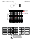
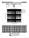
Damper Sizing Information
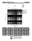
The following figure shows maximum damper section size.
Single Section
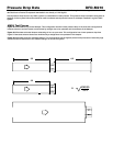
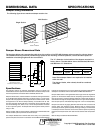
Damper Sleeve Dimensional Data
The drawings below and corresponding table show the position of the DFD-M210 damper when mounted in a factory sleeve.
The standard mounting locations provide enough space for the mounting of manual quadrant, controls and allow space for
installation of retaining angles and duct connections.
127mm
Right hand drive is shown
Left hand drive available upon request
LH RH
A
Sleeve Length
Varies
B*
S
T*
152mm
38mm max.
95mm
137mm
The “A” dimension is the location of the damper mounted in a
factory sleeve. The table below shows the Standard, Minimum,
and Maximum “A” dimensions.
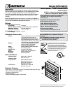
Specifications
Fire Dampers meeting the following specifications shall be furnished and
installed where shown on plans and/or as described in schedules. Dampers shall
meet the requirements of the latest edition of NFPA 80, 90A and 101.
Dampers shall be tested, rated and labeled in accordance with the latest edition
of UL Standard 555. Dampers shall have a UL 555 fire rating of 1
1
⁄2 hours. Each
damper shall be equipped with a heat responsive device which has been tested
and approved for use with the damper assembly in accordance with UL 555.
The heat responsive device shall have a temperature rating of (specifier select
one of the following) 74ºC, 100ºC, 141ºC, or 177ºC. Dampers shall be UL labeled
for use in dynamic systems. The damper shall have a dynamic closure pressure
rating of 1 kPa.
Damper actuator shall be manual quadrant. Manufacturers submittal data shall
indicate actuator space requirements around the damper.
The Damper Manufacturers submittal data shall certify all air performance
pressure drop data is licensed in accordance with the AMCA Certified Ratings
Program for Test Figures 5.2, 5.3 and 5.5. Damper air performance data shall be
developed in accordance with the latest edition of AMCA Standard 500-D.
Damper blades shall be 1.5mm galvanized steel 3V type with three longitudinal
grooves for reinforcement. Blades shall be completely symmetrical relative to
their axle pivot point, presenting identical resistance to airflow and operation in
either direction through the damper (blades that are non-symmetrical relative to
their axle pivot point or utilize blade stops larger than 13mm are unacceptable).
Damper frame shall be 16 gauge galvanized steel formed into a structural hat
channel shape with reinforced corners. Bearings shall be sintered bronze,
permanently lubricated, synthetic (acetal) sleeve type rotating in extruded holes
in the damper frame for maximum service. Axles shall be square and positively
locked into the damper blade. Jamb seals shall be stainless steel compression
type.
Basis of design is Greenheck Model DFD-M210.
Copyright © 2005 Greenheck Fan Corpation
DFD-M210 Rev. 3 June 2005
1
All dampers w/o OCI.
Note: Entire damper frame is not required to be installed
within the wall.
The damper blades, when closed, should be contained
in the wall.
H
w
1270mm
813mm
1626mm
914mm x 914mm
or
813mm x 1270mm
Multi Section
GREENHECK
Greenheck Kunshan Co Ltd.
17 Qunyi Minying District • Kunshan Economic &
Technical Development Zone
Kunshan, Jiangsu, China 215300
Tel: 0512-573-66666 • Fax: 0512-573-78633
www.greenheck.com
"A" Dimension
Standard Minimum Maximum
All Dampers 183mm 137mm 406mm