


9
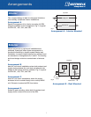
Arrangements
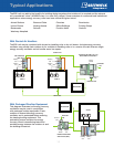
This compact design is ideal for the space limitations
that routinely complicate interior installations.
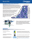
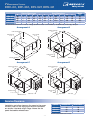
Arrangement A
Specify Arrangement A for interior mounting. All ERV
sizes are available in this arrangement. Fig.1 is typical
for ERV-251, -361, -521, and -581.
Intake Hood
Intake Hood
Supply
Air
Exhaust Air
Top View
Top View
Exhaust
Hood
Intake Hood
Supply Air
Exhaust Air
Exhaust Air
Top View
Exhaust
Hood
Duct
Supply Air
Exhaust Air
Top View
Exhaust
Hood
Duct
Supply Air
Arrangement A - Interior Mounted
Fig. 1
Intake Hood
Intake Hood
Supply
Air
Exhaust Air
Top View
Top View
Exhaust
Hood
Intake Hood
Supply Air
Exhaust Air
Exhaust Air
Top View
Exhaust
Hood
Duct
Supply Air
Exhaust Air
Top View
Exhaust
Hood
Duct
Supply Air
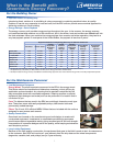
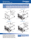
Arrangement B - Roof Mounted
Fig. 2
Interior
Exterior
Where roof mount or pad mount installations are
preferred, Greenheck offers three arrangements to
provide the flexibility to simplify system design and
installation. Louvered intake hood and an exhaust hood
are standard on Arrangements B, C and D. The housing
and hood design minimize re-entrainment of exhaust
air.
Arrangement B
Ideal for roof mount installations where both exhaust and
supply ducts penetrate the roof deck and attach to the
bottom of the energy recovery ventilator. Fig. 2 is typical
for ERV-251, -361, -521, and -581.
Arrangement C
Ideal for roof mount installations where the supply
airstream is to be routed directly into a rooftop HVAC
unit. Exhaust air enters the ERV from below.
Arrangement D
Suited for pad mounting, where both the exhaust and
supply ducts connect to the end of the ERV.