


19
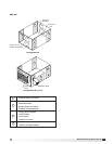
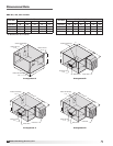
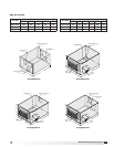
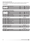
Model ERV Energy Recovery Unit
Rotation Sensor
The rotation sensor monitors energy recovery wheel
rotation. If the wheel should stop rotating, the sensor
will close a set of contacts in the unit control center.
Field wiring of a light (or other alarm) between
terminals R & 12 in the unit control center will notify
maintenance personnel when a failure has occurred
(refer to Remote Panel Wiring Schematics section for
wiring details).
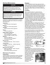
Dirty Filter Sensor
Dirty filter sensors monitor pressure drop across the
outdoor air filters, exhaust air filters or both. If the
pressure drop across the filters exceeds the set point,
the sensor will close a set of contacts in the unit
control center. Field wiring of a light (or other alarm)
to these contacts will notify maintenance personnel
when filters need to be replaced.
The switch has not been set at the factory due to
external system losses that will affect the switch. This
switch will need minor field adjustments after the
unit has been installed with all ductwork complete.
The dirty filter switch is mounted in the exhaust inlet
compartment next to the unit control center or in unit
control center.
To adjust the switch, the unit must be running with
all of the access doors in place, except for the
compartment where the switch is located (exhaust
intake compartment). Model ERV units require the
opening around the control center to be covered (with
cardboard, plywood, etc.) to set up the dirty filter
switch.
The adjusting screw is located on the top of the
switch. Open the filter compartment and place a
sheet of plastic or cardboard over 50% of the filter
media. Replace the filter compartment door. Check to
see if there is power at the alert signal leads (refer to
electrical diagram).
Whether there is power or not, turn the adjustment
screw on the dirty filter gauge (clockwise if you did
not have power, counterclockwise if you did have
power) until the power comes on or just before the
power goes off. Open the filter compartment and
remove the obstructing material. Replace the door
and check to make sure that you do not have power
at the alert signal leads. The unit is now ready for
operation.
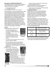
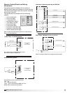
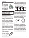
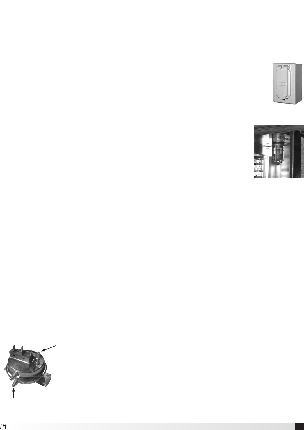
Setscrew (on front of switch) must
be manually adjusted after the
system is in operation.
Negative pressure connection
is toward the ‘front or top’ of
the switch. (senses blower side
of filters)
Positive pressure connection is toward the ‘back or
bottom’ of the switch. (senses air inlet side of filters)
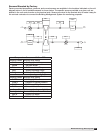
CO
2
Sensor
This accessory is often used to provide a modulating
control signal to a variable frequency drive to raise
and lower airflow in relationship to the CO
2
levels
in the space. This strategy is often referred to as
Demand Control Ventilation and provides further
energy savings to the system. Follow instructions
supplied with sensor for installation and wiring details.
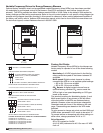
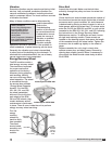
Service Outlet
120 VAC GFCI service outlet ships
loose for field installation. Requires
separate power source so power is
available when unit main disconnect is
turned off for servicing.
Vapor Tight Lights
Vapor tight lights provide light to each of the
compartments in the energy
recovery unit. The lights are wired
to a junction box mounted on the
outside of the unit. The switch to
turn the lights on is located in the
unit control center. The switch
requires a separate power source
to allow for power to the lights
when the unit main disconnect is
off for servicing.