


4
Series L: Models LB, LBP, LD, and LDP
®
Removing From Storage
As fans are removed from storage to be installed
in their final location, they should be protected
and maintained in a similar fashion until the fan
equipment goes into operation.
Pre-Startup Checks
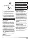
1. Check all fasteners for tightness. The wheel
should rotate freely and be aligned as shown in
Figure 1.
2. Wheel position is preset and the unit is test
run at the factory. Movement may occur during
shipment, and realignment may be necessary.
3. Centering can be accomplished by loosening
the bolts holding the drive frame to the shock
mounts and repositioning the drive frame.
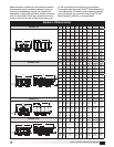
4. Wheel and inlet cone overlap can be adjusted
by loosening the setscrews in the wheel and
moving the wheel to the desired position.
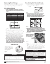
5. Check wheel rotation by momentarily energizing
the unit. Rotation should be clockwise as shown
in Figure 2 and correspond to the rotation decal
on the unit. Rotation is determined when the unit
is viewed from the motor or shaft pulley side.
Pre-Starting Belt Tension Checks
6. Always loosen tension enough to install belt
without stretching, see Figure 3.
7. If adjustments are made, it is very important
to check the pulleys for proper alignment.
Misaligned pulleys lead to excessive belt wear
vibration, noise and power loss, see Figure 4.
8. Belt tension can be adjusted by loosening four
fasteners (marked “R” in Figure 5) on the drive
frame. This allows the motor plate to slide on the
drive frame angles for proper positioning.
9. Belt tension should be adjusted to allow
1
⁄64 in.
(0.397 mm) of deflection per inch of belt span.
For example, a 15 in. (381 mm) belt span should
have
15
⁄64 in. (0.234 mm) (or about
1
⁄4 in. (6 mm))
of deflection with moderate thumb pressure at
mid-point between pulleys, see Figure 6.
Belt Span
G
C
l
o
c
k
w
i
s
e
CORRECT WRONG WRONGWRONG
64
Deflection =
Belt Span
WHEEL ROTATION
All Series L fans have
clockwise (CW) wheel
rotation when viewed
from top of fan.
Figure 2
WARNING
Correct direction of wheel rotation is critical.
Reversed rotation will result in poor air
performance, motor overloading and possible
motor burnout.
Do not force belt(s). Forcing the
belt(s) will break the cords and
cause belt failure
.
BELTS
Figure 3
WARNING
The fan has been checked for mechanical noises at
the factory prior to shipment. If mechanical noise
should develop, suggested corrective actions are
offered in the Troubleshooting section.
WARNING
Over tightening will cause excessive bearing wear
and noise. Too little tension will cause slippage at
startup and uneven wear.
Figure 4
FASTENERS
*Identical fasteners on
opposing side must
also be loosened.
Figure 5
R
G
H
WHEEL OVERLAP AND GAP DIMENSIONS
Model G - Overlap in. (mm) H - Gap in. (mm)
LD/LDP 60-095 –
3
⁄32 (2)
LD/LDP 100-120 –
1
⁄4 (6)
LB/LBP 10-14
1
⁄4 (6) –
LB/LBP 18-24
3
⁄8 (10) –
LB/LBP 30-54
1
⁄2 (13) –
Figure 1