


1. DAMPER IS INSTALLED OUTSIDE OF WALL PLANE
OFSD-XXX
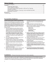
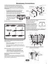
Figure 1 shows two approved installations for
combination fire smoke dampers: 1) “Through the
grille access” and 2) installation in continuing duct.
To provide "through the grille" access to the damper
actuator, the damper is located toward the back of the
sleeve and the actuator is installed between the damper
and grille. Actuator and damper can be accessed and
serviced by removing the grille. To provide access to the
damper actuator for continuing ductwork, refer to the
requirements of NFPA 90A.
ODFD-XXX, OFD-XXX, and OSSFD-XXX: Figure
1 shows two installations that are also approved for
curtain fire dampers. For access to inspect the damper
and fusible link, refer to the requirements of NFPA 90A.
2. CLEARANCE REQUIREMENTS
There is no minimum clearance requirement between
the wall/floor opening and the sleeve exterior (with
thermal blanket attached). However, to facilitate
installation, clearances between the wall/floor opening
and the damper sleeve are recommended. although
there is no maximum allowable clearance, the minimum
overlap requirements between the wall/floor and the
flange/retaining angle must be met. On grill mount
installations the flange must overlap the wall/floor by
1⁄2 in. (13mm). On continuous duct installations, the
retaining angles must overlap the wall/floor by 1 in.
(25mm). Because no clearances are required betweeen
the wall/floor opening and the sleeve, dampers may not
be installed in the plane of the wall using this installation
method.
3. DUCT TO SLEEVE CONNECTIONS
Dampers are supplied with actuators (on applicable
models) and sleeves from the factory and can be
installed without the need for additional field installed
sleeves.
Sleeve gauges of 20-14 (.9mm - 2mm) are to be used.
UL Standard 555 requires all ducts to terminate at fire
damper sleeves. Sleeve thickness must not be less than
the gauge of the connecting duct.
Duct to sleeve breakaway connections must be of the
type described on page 5. Factory furnished round duct
collars on type R and CR dampers are also considered
to be breakaway connections and may be used.
Steel stud
5/8 in . x 1 in. 16 ga.
angles minimum
(Refer to Section 4)
Grille
(Supplied
by others)
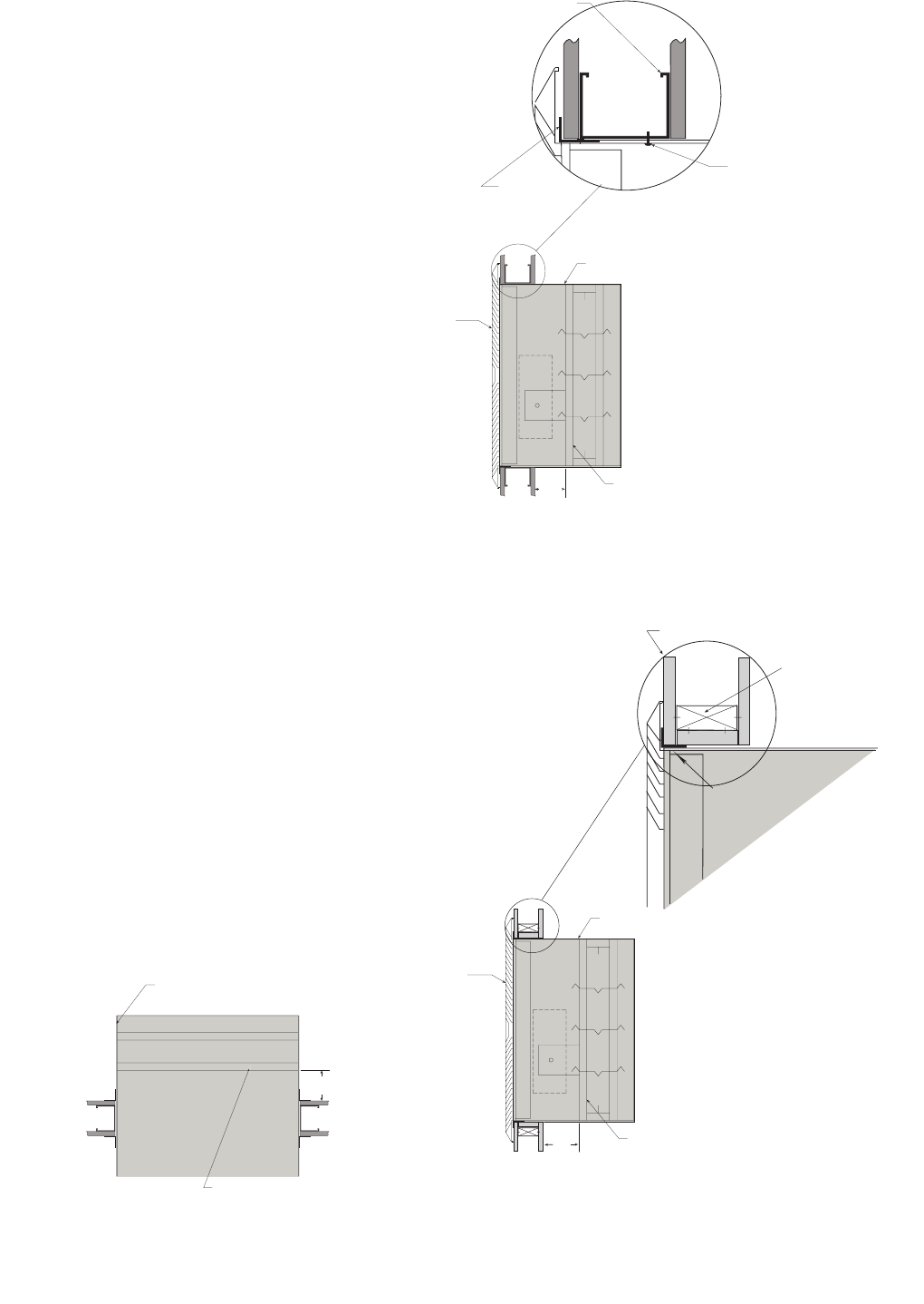
Factory Supplied
Thermal Blanket
Factory Supplied
Thermal Blanket
7 1/2 in.
Max.
7 1/2 in.
Max.
Fire damper or
combination fire
smoke damper
Fire damper or
combination fire
smoke damper
#10 sheet metal screws
spaced 6 in. on center and
maximum of 2 in. from the
corners (minimum of 2
screws per side). Screw into
rear portion of the studs so
as to avoid space conflicts
with the grille assembly.
“Duct Continues”
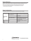
Note: Both installations may be vertical or horizontal.
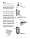
W
ooden Stud Construction
Gypsum Wallboard
Stud or Runner
1in. x 1 in. 16 ga.
angle minimum
(Refer to section 4)
(Duct Terminates)
In wood stud construction,
gypsum wallboard must cover
all wood stud surfaces.
Grille
(Supplied
by others)
Factory Supplied
Thermal Blanket
Fire damper or
combination fire
smoke damper
6 1/2 in.
Max.
Figure 1: Installation configurations for ‘Out of Wall’ curtain fire dampers and combination fire smoke dampers.
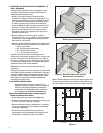
“Duct Terminates” Metal Stud
“Duct Terminates” Wood Stud
Steel stud
5/8 in . x 1 in. 16 ga.
angles minimum
(Refer to Section 4)
Grille
(Supplied
by others)
Factory Supplied
Thermal Blanket
Factory Supplied
Thermal Blanket
7 1/2 in.
Max.
7 1/2 in.
Max.
Fire damper or
combination fire
smoke damper
Fire damper or
combination fire
smoke damper
#10 sheet metal screws
spaced 6 in. on center and
maximum of 2 in. from the
corners (minimum of 2
screws per side). Screw into
rear portion of the studs so
as to avoid space conflicts
with the grille assembly.
3