


'BDUPSZTVQQMJFE
UIFSNBMCMBOLFU
BSPVOETMFFWF
$PNCJOBUJPO'JSF
4NPLF%BNQFS
'JSF
SBUFE
CBSSJFS
c
.BY
3FHJTUFS
JODMVEFT
HSJMMFBOE
0#%
4MFFWF-FOHUI
9
"
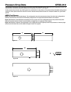
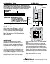
Actuator Space Envelopes
The drawing below and corresponding table show the minimum dimensions
required for internal actuator mounting on OFSD-312s. The standard mounting
locations provide enough space for the mounting of actuators and controls plus
allowing space for a grille and duct connection (see Sleeve Length below).
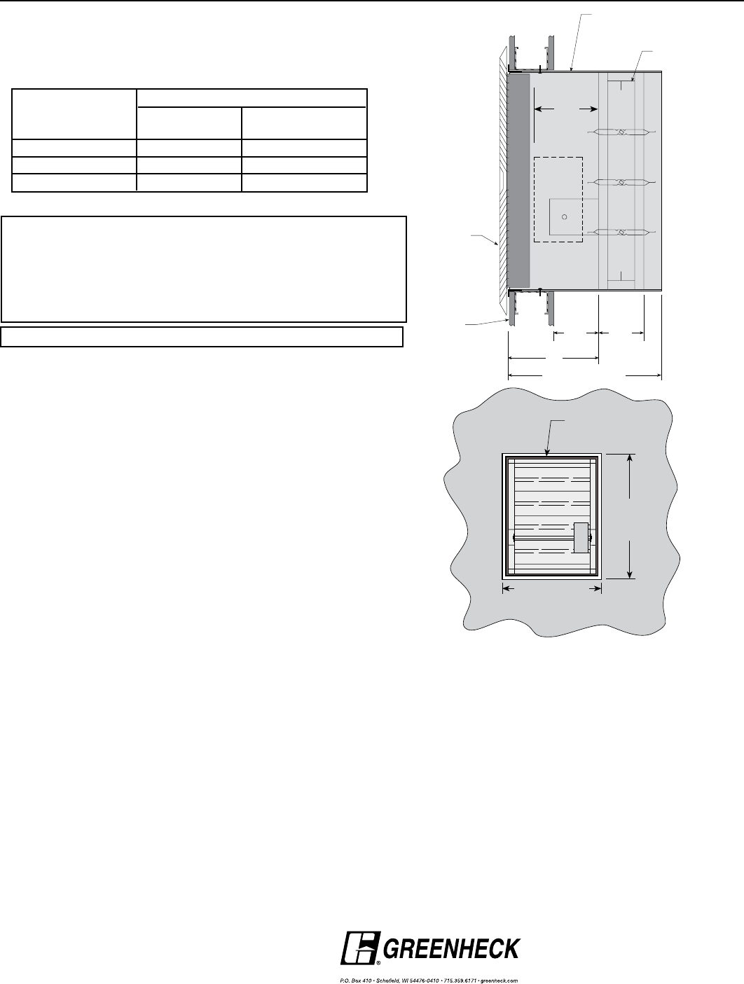
Wall Opening Sizing
To accommodate for sleeve and thermal blanket thickness,
the wall opening must be oversized by
3
⁄8
in. (9.5mm) as
shown. For example, if the nominal damper size required
is 18 in. x 14 in. (457mm x 356mm), the wall opening size
needs to be 18
3
⁄8
in. x 14
3
⁄8 in. (467mm x 365mm). The
damper itself is undersized
1
⁄4 in. (6mm) on each dimension
for an actual damper size of 17
3
⁄4
in. x 13
3
⁄4
in. (451mm x
349mm). This is also the inside dimensions of the sleeve (for
grille considerations).
Actuator Space
Honeywell
Envelopes
ML-4XXX series MS-4120 series
MS4XXX series
‘X’ Dimension 5.88 in.(149mm) 5.88 in. (149mm)
Minimum Width 12 in. (305mm) 12 in. (305mm)
Minimum Height 12 in. (305mm) 12 in. (305mm)
Application Data OFSD-312
Sleeve Information
‘Sleeve Length’ = Depth of Grille (or Register)
+ X (Actuator: see table above)
+ 5 in.[127mm] (Damper Width)
+ 1.25 in.[31.8mm] (for duct connection)
(round up to nearest length: 14 in., 16 in., 18
in., or 20 in. [356, 406, 457, 508mm])
‘Sleeve Gauge’ = 16 Ga. or 20 Ga. (1.5mm or 1mm)
Nominal Damper
Width +
3
8
in.
Nominal
Damper
Height +
3
/
8
in.
Wall
Fire Smoke Damper
With Sleeve And
Thermal Blanket
/
Combination Fire Smoke Dampers meeting the following
specifications shall be furnished and installed where shown on
plans and/or as described in schedules. Dampers shall meet the
requirements of NFPA 80, 90A, 92A, 92B, 101 & 105 and further shall
be tested, rated and labeled in accordance with the latest edition
of UL Standards 555 and 555S. Dampers shall have a UL555 fire
rating of 1½ hours and be of low leakage design qualified to UL 555S
Leakage Class II.
Each damper shall be UL qualified for mounting out of the plane
of the wall to allow ‘through the grille’ access to actuator and
controls. Each damper /actuator combination shall have a UL555S
elevated temperature rating of 250° F (121ºC) minimum and shall
be operational and dynamic rated to operate at maximum design air
flow at its installed location. Each damper shall be supplied with an
appropriate actuator installed by the damper manufacturer at the
time of damper fabrication.
Damper actuator shall be (specifier select one of the following)
electric type for 120 (24 or 230) Volt operation. Each damper shall be
UL555S rated for leakage and airflow in either direction through the
damper.
Damper blades shall be of the double skin airfoil type and shall
have an equivalent thickness of 14 ga. (2mm) Damper frame shall
be galvanized steel formed into a structural hat channel shape with
reinforced corners. Bearings shall be sintered bronze sleeve type
rotating in extruded holes in the damper frame. Blade edge seals
shall be silicone rubber designed to inflate and provide a tighter seal
against leakage as pressure on either side of the damper increases.
Jamb seals shall be stainless steel compression type. Blades shall be
completely symmetrical relative to their axle pivot point, presenting
identical resistance to airflow in either direction or pressure on either
side of the damper.
Each damper shall be supplied with a factory mounted sleeve; sleeve
shall be wrapped with UL approved thermal barrier material. Each
damper shall be supplied with a 165°F (74ºC) RRL.
The basis of design is Greenheck Model OFSD-312.
Specifications
Copyright ©2006 Greenheck Fan Corporation
OFSD-312 Rev 3 June 2006