


INTAKE
DISCHARGE
DISCHARGE
INTAKE
C
L
C
L
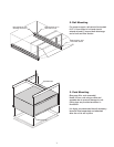
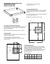
Equipment
Support
Footprint
C
L
A
A
(fig.4)
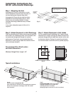
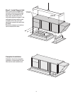
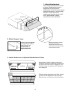
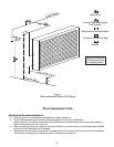
Roof mounted arrangement HZ
with weatherhood, mounted on three equipment supports.
Ductwork is attached to discharge collar with rubber
boot transition.
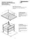
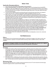
(fig.5)
Arrangement HZ shown as an indoor
hanging installation with intake and
discharge ductwork installed.
(Hanging support structure for unit is by others).
(fig.2) (fig.3)
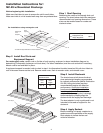
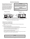
Step 1 Mounting the Unit
Arrangement HZ can be mounted on a curb
with an equipment support (see curb inst.) or
on three equipment supports (figs.1&4).
Arrangement HZ can also be used for indoor
applications mounted hanging (fig. 5), inline
as part of an air handling system, or base
mounted. Mounting hardware to be provided
by others.
In any case, adequate support of the unit is
required.
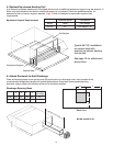
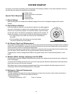
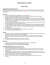
Step 2 Attach Ductwork to Unit Discharge
Chart and drawing (fig.2) below shows opening size (ID)
and location for a discharge collar. Also included is the
recommended straight duct length for optimal
performance. Greenheck recommends attaching
ductwork to collar using a rubber duct section at the
unit to eliminate vibration.
Step 3 Attach Ductwork to Unit Intake
For non-weatherhood installations, fig. 3 below shows
dimensions for supply opening (ID). Attach ductwork to
perimeter flange using a rubber duct section at the unit
to eliminate vibration. Design the remaining ductwork
for minimal losses to allow the unit to operate properly.
A -Equip. Support C
L
44
1
/4"
(fig.1)
Typical Installations
3
Recommended Duct Size/Location
and Intake Dimensions
Minimum Straight Duct Length - 54”
16
16
48
43
12
23
Installation Instructions for:
NV-45 w/Horizontal Discharge