


14
Model PVe Heat Recovery Unit
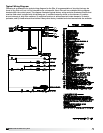
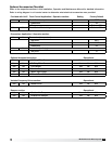
Typical Wiring Diagram
Following is an example of a typical wiring diagram for the PVe. It is representative of circuitry that may be
found in any PVe unit, but it is not intended to be unit-specific. Each PVe unit has a detailed wiring diagram
located within the control panel. This diagram illustrates typical factory wiring and also illustrates circuits that
must be field wired. Included with this drawing are 1) variable frequency drives on the blowers, 2) outdoor
air and exhaust air dirty filter switches, 3) motorized outdoor air and exhaust air intake dampers, 4) electric
preheater, and 5) timed exhaust frost control. Many other factory installed and wired accessories are available.