


7
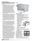
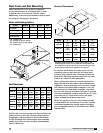
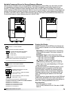
Model PVe Heat Recovery Unit
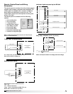
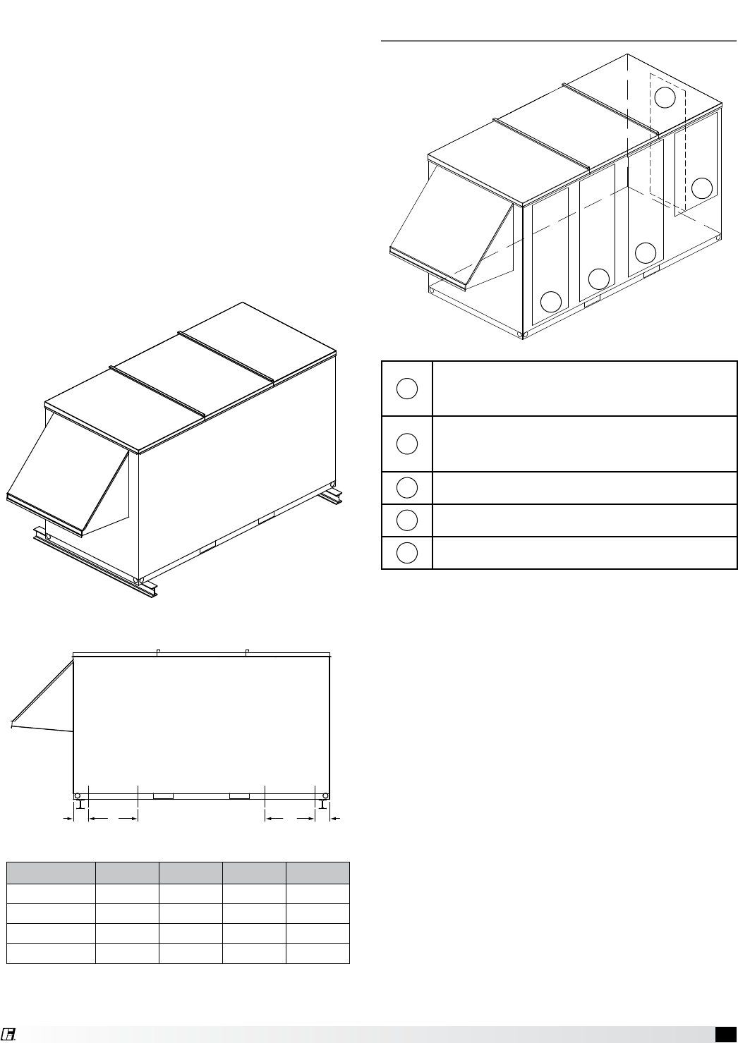
Isometric view of
PVe on rails
Side view of
PVe on rails
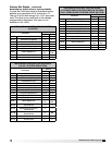
Unit Size A
B* C* D
PVe-20 5 14 13.25 7.75
PVe-35 5 14 12.00 6.50
PVe-45 5 14 15.50 10.5
PVe-55 5 14 18.75 13.25
All dimensions are shown in inches.
*Zones B and C identify regions/zones where rails may
not be place due to ductwork.
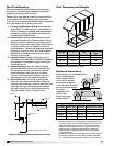
Rail Mounting / Layout
An alternative method of unit installation is to mount
the unit on rails supplied by others. The purpose of
mounting the unit on either rails or the GKD curb is to
elevate the unit away from moisture conditions and
to provide proper clearance for installation of water
drain traps.
• Rails should be designed to handle the weight of
the PVe unit, taking into consideration weight per
square inch on bearing surfaces. Rails should be
positioned as shown in the drawing below, taking
into consideration proper load distribution and
support by roof support elements.
• Make sure that rail positioning does not interfere
with either the RA Intake duct or the optional
straight down SA Discharge duct.
• Rails should extend beyond the unit a minimum
of 12 inches.
• Set unit on rails.
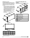
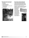
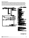
Access Panel Description and
Location
1
Filters
Optional OA Damper
Optional RA Damper
2
Optional Face and Bypass Dampers
Plate Heat Exchanger
Optional Preheater
3
Plate Heat Exchanger
4
Control Center
5
Blowers
1
2
3
4
5
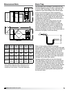
D
C
A B
D
C
A B