


10
System
Considerations
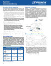
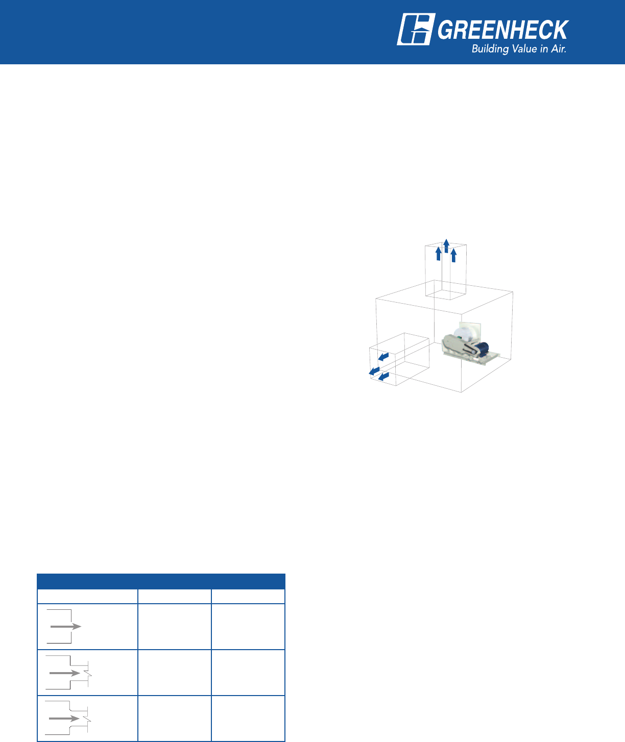
Air Plenum Design Guidelines
To assure optimum performance and be able to use
the system effect coefficients below, the following
guidelines should be adhered to in the plenum design:
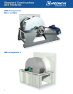
1. Flexible connections at the inlet are recommended to
isolate vibration. The inlet connection can be square
(connected to the inlet panel) or round (connected
to an optional inlet collar).
2. Plenum walls should be at least one-half of a wheel
diameter away from the fan.
3. Dampers or coils should be at least three-quarters
of a wheel diameter away from the fan to assure an
even velocity distribution through them.
4. For fans operating in parallel:
Have one wheel diameter clearance between
adjacent fans.
#BDLTUPQDMVUDIFTPSCBDLGMPXDPOUSPMEBNQFST
should be used to prevent windmilling of wheels if
fans are started or stopped at different times.
Do not select fans near the top of the fan curve to
prevent unstable operation.
8IFFMTTIPVMECFTFMFDUFEBTDPOUSBSPUBUJOH
$8$$8$8FUDUPJNQSPWFBJSGMPXQBUUFSOT
between the fans.
See AMCA Publication 201 for additional information
on this subject.
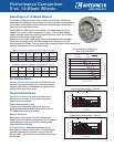
Duct System Effect
Reduction in cataloged air performance due to a plenum
around the fan is called a system effect. System effect
is a pressure loss, which must be added to the total
external static pressure of the duct system in order to
make the proper fan selection from catalog data. The
pressure loss calculation is based on the velocity of
the air in the discharge ductwork. As shown below, it
is derived by multiplying the appropriate coefficient by
the velocity pressure.
Effects of Air Density
Ratings in the fan performance tables and curves of
this catalog are based on standard air: clean and dry
XJUIBEFOTJUZPGMCTGU
3
at 70°F at a pressure of
29.92 in. of mercury. A change in elevation, temperature
or the type of gas handled will affect density. A fan
running at a constant speed and installed in a fixed
system will experience changes in pressure output and
horsepower consumption if the density of the airstream
varies. The air volume delivered by the fan will remain
constant regardless of air density.
Example of Performance Correction
Select a fan to meet the following requirements:
7PMVNF DGN
4UBUJD1SFTTVSF JOXH
Airstream Temperature: 70°F
Installation Elevation: 13,000 ft.
Plenum Discharges (ducted): 24 in. x 27 in. Radial
24 in. x 27 in. Axial
1. The selection is at non-standard atmospheric
conditions and must be corrected to standard
DPOEJUJPOT UP VTF DBUBMPHFE EBUB 7PMVNF SFNBJOT
at 20,000 cfm, since the volume delivered is not
affected by air density.
2. An air density correction factor must be applied to
the static pressure. For an elevation of 13,000 ft. and
a temperature of 70°F, 1.6 is the required correction
GBDUPS5BCMF"6TFUIFDPSSFDUJPOGBDUPSUPBEKVTU
the static pressure by multiplying the required static
pressure by the correction factor.
JOXHYJOXH
Discharge Configuration Coefficients
Discharge Radial Axial
Unducted
2.0 2.3
Ducted
1.8
Ducted
with Bell
1.1 1.4
5"#-&%JTDIBSHF$PFGGJDJFOUT
24 in. x 27 in.
(Radial)
24 in. x 27 in.
(Axial)