


3
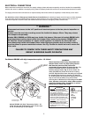
Belt Span
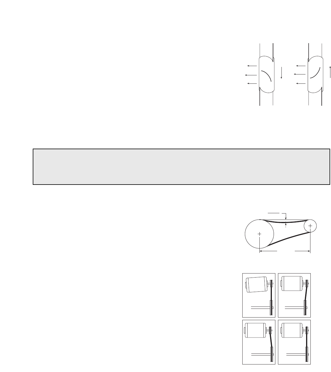
Deflection =
Belt Span
64
ROUTINE MAINTENANCE
Once the fan has been put into operation, a periodic maintenance program should be set up to preserve the reliability
and performance of the fan. Items to be included in this program are:
• BELTS
• BEARINGS
• FASTENERS
• SET SCREWS
• LUBRICATION
• REMOVAL OF DUST/DIRT
WRONG WRONG
WRONG CORRECT
WARNING
DISCONNECT AND SECURE TO THE “OFF” POSITION ALL ELECTRICAL POWER TO THE FAN
PRIOR TO INSPECTION OR SERVICING. FAILURE TO COMPLY WITH THIS SAFETY PRECAUTION
COULD RESULT IN SERIOUS INJURY OR DEATH.
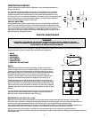
Fig. 5
Fig. 6
BELTS
Premature belt failures are frequently caused by improper belt tension
(either too tight or too loose) or misaligned pulleys. The proper tension for
operating a V-belt is the lowest tension at which the belts will not slip at
peak load conditions. For initial tensioning, the proper belt deflection half
way between pulley centers is
1
/64" for each inch of belt span. For
example, if the belt span is 64 inches, the belt deflection should be one
inch using moderate thumb pressure at midpoint of the drive (Fig. 5).
Check belt tension two times during the first 24 hours of operation and
periodically thereafter. To adjust belt tension, simply loosen four fasteners
(two on each side of the motor plate) and slide the motor plate away from
the fan shaft until proper belt tension is attained. On some fans, fasteners
attaching the motor to the motor plate must be loosened in order to adjust
the belt.
It is very important that the drive pulleys remain in proper alignment after
adjustments are made. Misalignment of pulleys will result in premature
belt wear, noise, vibration and power loss. See Fig. 6.
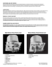
Airflow
Airflow
Rotation
Rotation
PRESTARTING CHECKS
Check all fasteners and set screws for tightness. This is especially important for
bearing set screws.
The propeller should rotate freely and not rub on the fan panel venturi. Rotation
direction of the propeller should be checked by momentarily turning the unit on.
Rotation should be in the same direction as the rotation decal affixed to the unit
or as shown in Fig. 4. For 3-phase installations, fan rotation can be reversed by simply
interchanging any two of the three electrical leads. For single phase installations
follow the wiring diagram located on the motor.
FOR BELT DRIVE FANS
The adjustable motor pulley is preset at the factory for the specified fan RPM. Fan
speed can be increased by closing or decreased by opening the adjustable pulley.
Two or three groove variable pitch pulleys must be adjusted an equal number of turns
open. Any increase in fan speed represents a substantial increase in horsepower
required from the motor. Always check motor load amperage and compare to name
plate rating when changing fan speed.
Fig. 4
BEARINGS (For belt drive fans only)
Bearings are the most critical moving part of the fan and should be inspected at periodic intervals. Locking collars
and set screws, in addition to fasteners attaching the bearings to the bearing plate, must be checked for tightness. In a
clean environment and temperatures above 32°F./below 200° F., fan shaft bearings with grease fittings
should be lubricated semi-annually using a high quality lithium based grease. If unusual environmental conditions exist
temperatures below 32°F./above 200°F., moisture or contaminants, more frequent lubrication is required.
With the unit running, add grease very slowly with a manual grease gun until a slight bead of grease forms at
the seal. Be careful not to unseat the seal by over lubricating or using excessive pressure. Bearings without grease fittings are
lubricated for life.