


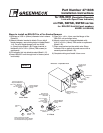
Resettable Reusable Link/
Open-Closed Indicator
Note: The switch wires wrapped with a
blue marker indicate the closed position
of the damper.
Electrical Capacity = 10 AMP (max)
Orange
Black Black White
Yellow
Yellow
Yellow
Yellow
NC
NC
NO
NO
P = Primary Temperature Sensor
P
Optional Momentary Contact
Test Switch
S1
S2
Electric Damper
Actuator or Pneu.
Solenoid Valve
Damper
Indicator
LIghts
By Others
Wiring Diagram
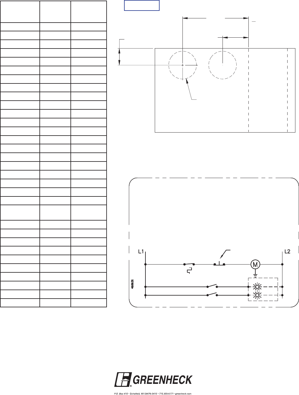
Note: Operator Mounted Upside-Down On Steel Airfoil Units From 10 in. to 17 in. (254mm to 432mm) High
D
Ø3.625
>11" NOM HEIGHT
< 11" NOM HEIGHT
8.375
3.563
SURF ACE
INSIDE
Detail 2
All dimensions shown in inches.
Nominal
Section Height
(in.)
3V
Style
Steel Airfoil
Style
6-7 2.625 2.625
8 3.125 3.125
9 3.625 3.625
10-11 2.625 3.625
12-13 2.625 4.125
14-15 3.125 4.625
16 3.625 5.125
17 4.125 5.625
18 13.125 13.125
19 14.125 14.125
20 14.625 14.625
21 15.625 15.625
22 16.625 16.625
23 17.125 17.125
24 18.125 18.125
25 19.625 19.625
26 20.625 20.625
27, 39-41 21.625 21.625
28, 42 22.125 22.125
29, 43. 57 23.125 23.125
30, 44, 58 24.125 24.125
31, 45, 55-56,
59
25.125 25.125
32 26.625 26.625
33, 47 27.625 27.625
34, 46 28.625 28.625
35, 49 29.125 29.125
36, 48 30.625 30.625
37, 51 31.125 31.125
38, 50, 52 32.125 32.125
53 23.625 23.625
54 24.625 24.625
60 4.125 4.125
Copyright © 2008 Greenheck Fan Corporation
RRL/OCI Rev 1 July 2008