


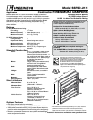

Damper Sizing Information
Specifications
Combination Fire Smoke Dampers meeting the following specifications
shall be furnished and installed where shown on plans and/or as
described in schedules. Dampers shall meet the requirements of the
latest edition of NFPA 80, 90A, 92A, 92B, 101, & 105 and further shall
be tested in accordance with the latest edition of UL Standards 555
and 555S. Dampers shall have a UL 555 fire rating of 1
1
⁄2 hours and be
of low leakage design qualified to UL555S leakage class I.
Each damper /actuator combination shall have a UL555S elevated
temperature rating of 250°F (121°C) minimum and shall be operational
and dynamic rated to operate at maximum design air flow at its
installed location. Each damper shall be supplied with an appropriate
actuator installed by the damper manufacturer at the time of damper
fabrication. Damper actuator shall be (specifier select one of the
following) electric type for 120 (24 or 230) volt operation or pneumatic
type for 25 psi minimum (30 psi maximum) operation.
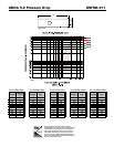
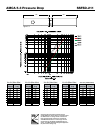
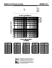
The Damper Manufacturers submittal data shall certify all air
performance pressure drop data is licensed in accordance with the
AMCA Certified Ratings Program for Test Figures 5.2, 5.3 and 5.5.
Damper air performance data shall be developed in accordance with
the latest edition of AMCA Standard 500-D. Dampers shall be labeled
with the AMCA Air Performance Seal.
Damper blades shall be 16 ga. (1.5mm) 304 stainless steel 3V type
with three longitudinal grooves for reinforcement. Blades shall be
completely symmetrical relative to their axle pivot point, presenting
identical resistance to airflow and operation in either direction through
the damper (blades that are non-symmetrical relative to their axle pivot
pointorutilizebladestopslargerthan1/2in.[13mm]areunacceptable).
Damper frames shall be 304 stainless steel formed into a structural hat
channel shape with reinforced corners. Bearings shall be 304 stainless
sleeve type rotating in extruded holes in the damper frame. Jamb seals
shall be stainless steel compression type.
AllUL555 and555SDynamicClosureRatings,Operational Ratings
and Leakage Ratings shall be qualified for airflow and pressure in
either direction through the damper. UL ratings shall allow for mounting
damper vertically (with blades running horizontal) or horizontally.
Basis of design is Greenheck Model SSFSD-211.
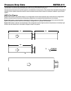
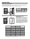
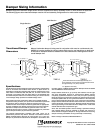
Dampers larger than maximum single section size are supplied as a factory assembly of two or more sections of equal size.
The following figures show maximum damper section size and assembly configurations for multi-section dampers.
Single Section
30”
24”
30”
24”
48”
Multi Section
Transitioned Damper
Dimensions
When a fire/smoke damper is being used in conjunction with round or oval ductwork, the
SSFSD-211 can be supplied in a factory sleeve with round or oval transitions on both ends
of the sleeve. Dampers should be ordered to the duct dimensions. Drawings below show
overall damper size.
*
These dimensions are furnished approximately
1
/4 in.
(6mm) undersize, except round and oval dimensions which
are approximately
1
/8 in. (3mm) undersize.
T
s
= (2)(Sleeve Thickness)
D* +
2 in. (51mm) +T
s
D*
TYPE R
16 in. (406mm)
Min.
2
1
/
8
in.
D* + 2 in. (51mm)+T
s
TYPE O
W
*
H*
W*
+ 2 in. (51mm)+T
s
H* + 2 in. (51mm)+T
s
W*
H*
TYPE C
H* + 2 in. (51mm)+T
s
(54mm)
16 in. (406mm)
Min.
2
1
/
8
in.
(54mm)
16 in. (406mm)
Min.
W* + 2 in. (51mm)+T
s
(54mm)
2
1
/
8
in.
Copyright© 2008 Greenheck Fan Corporation
SSFSD-211 Rev. 5 March 2008