


General Information
To ensure a successful installation, the instructions in
this manual should be read and adhered to. Failure to
comply with proper installation procedures may void the
warranty.
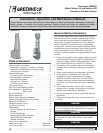
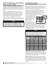
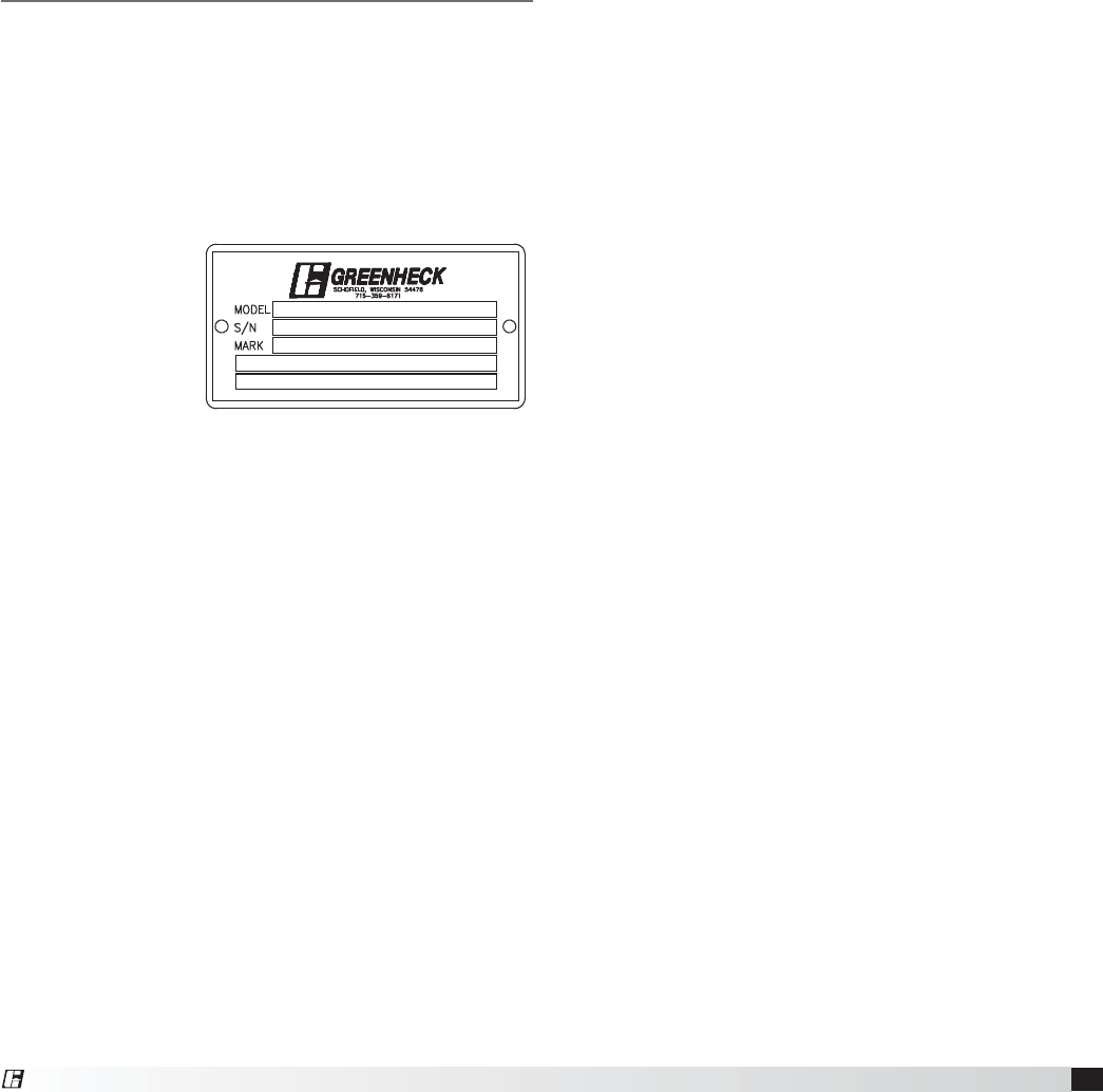
Unit and System Identification Tags
Each fan has a permanently affixed manufacturer’s
engraved metal nameplate containing the model
number and individual serial number.
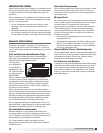
The tag shown
is an example of
an identification
nameplate on the
fan. The information
provides general
details about
the fan, as well as containing specific information
unique to the unit. When contacting your Greenheck
representative with future needs or questions, please
have the information on this label available. Tags are
mounted in an area which is clearly visible, usually on
the side of the fan cabinet.
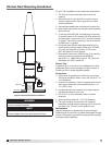
Vektor fan systems may arrive in component pieces
due to shipping restrictions. Individual components of a
system have matching identification tags which should
be used to identify and assemble the complete system.
Assembling systems with different identification tags
can cause reductions in the fan(s) performance.
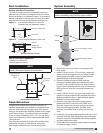
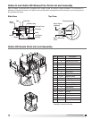
Prior to fully assembling and installing the Vektor-H or
Vektor-HS fans, inspect bypass air plenums and the fan
assembly to make sure they are in working order.
Pre-Installation Information
Before installation, it is important to be certain the
mounting surface will bear the operating weight of the
unit. For proper unit operation, it is also important that it
be operated in a completely level position.
For further details on safety practices involving
industrial and commercial fans, please refer to AMCA
Publication410.
REMOVING FROM STORAGE
As fans are removed from storage to be installed in their
final location, they should be protected and maintained
in a similar fashion, until the fan equipment goes into
operation.
Prior to assembly and installation of the Vektor fan and
system components, inspect the fan assembly to make
sure it is in working order.
1. Check all fasteners, set screws on the fan, wheel,
bearings, drive, motor base and accessories for
tightness.
2. Rotate the fan wheel(s) by hand and assure no parts
are rubbing. Access to the wheel is obtained through
a bolted panel located on the side of the fan housing.
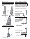
Electrical Disconnects
All fan motors should have disconnects located in close
visual proximity to turn off electrical service. Service
disconnects shall be locked-out when maintenance is
being performed.
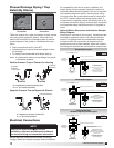
Moving Parts
All moving parts must have guards to protect personnel.
Refer to local codes for requirements as to the number,
type and design. Fully secure fan wheel before
performing any maintenance. The fan wheel may start
“free wheeling” even if all electrical power has been
disconnected. Before the initial start-up or any restart,
check the following items to make sure that they are
installed and secure.
t %POPUTQJOGBOXIFFMGBTUFSUIBOUIFNBYJNVN
cataloged fan rpm.
t "EKVTUNFOUTUPGBOTQFFETJHOJmDBOUMZBGGFDUTNPUPS
load. If the fan RPM is changed, the motor current
should be checked to make sure it is not exceeding
the motor nameplate amps.
Guards (Motor Cover, Weatherhoods)
Do not operate fans without proper protective devices in
place. Failure to do so may result in serious bodily injury
and property damage. Check local codes to ensure
compliance for all protective devices.
Air Pressure and Suction
In addition to the usual hazards associated with rotating
machinery, fans also create a dangerous suction at the
inlet. Special caution needs to be used when moving
around a fan, whether it is in operation or not. Before
start-up, make sure the inlet area is clear of personnel
and loose objects.
3
Laboratory Exhaust System
®