


Crathco
®
Remote Beverage Freezers Page 5
INSTALLATION
Shipment T
ransit
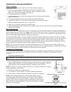
The freezer has been operated and tested at the factory. Upon arrival the complete
freezer must be thoroughly checked for any damage which may have occurred in
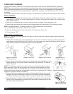
transit. NOTE: A Tip (N) Tell warning device is placed on each shipping carton at the
factory. If the arrow tip is blue, the carton has been tipped in transit. (see Figure B)
THE CARRIER IS RESPONSIBLE FOR ALL DAMAGE IN TRANSIT WHETHER
VISIBLE OR CONCEALED. DO NOT PAY THE FREIGHT BILL until the freezer has
been checked for damage. Have the carrier note any visible damage on the freight bill.
If concealed damage and/or shortage is found later, advise the carrier within 10 days
and request inspection. The customer must place any claim for damage and/or shortage
with the carrier. Grindmaster Corporation cannot make any claims against the carrier.
Installing your Freezer
1. Place the self-sealing rubber pad on a level counter stable and strong enough to
support the freezer’s weight. If equipped with legs instead of pad, install legs by
screwing them into the four leg holes on the bottom of the unit.
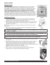
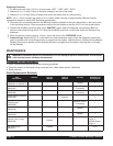
2. Make sure freezer is to be placed in a location that is within 6' of a properly grounded
circuit and allows adequate space for rear remote refrigeration connections and on
the sides for air circulation.
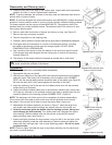
NOTE: Minimum clearance is 2" (5cm) on both sides and 8" (20cm) above the freezer.
(see Figure C)
3. Remove the side panels with a Phillips screwdriver and supporting all four sides, lift
machine up and place in appropriate area.
CAUTION: IF EQUIPPED WITH SPINNER DO NOT LIFT UNIT BY SPINNER SHAFT TO AVOID SERIOUS
DAMAGE TO SPINNER.
CAUTION: BEVERAGE FREEZERS ARE HEAVY PIECES OF EQUIPMENT. IT IS RECOMMENDED THAT
MOVING OR LIFTING THE UNIT BE DONE BY TWO PEOPLE TO AVOID INJURY.
CAUTION: FAILURE TO ALLOW ADEQUATE VENTILATION WILL VOID THE WARRANTY.
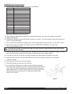
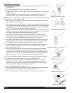
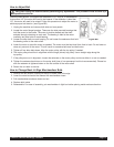
4. Remove cable tie used to secure motor during shipment. Make sure motor rocks freely.
(see Figure D)
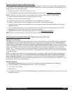
5. Connection of refrigeration system: The unit is supplied with mating quick disconnect
fittings. Removal of the rear panel will show: One 5/8” suction connection, one 3/8”
liquid connection for each barrel. Connect unit to condensing unit using the quick
disconnects supplied. Line sizing to the unit should be sized to minimize pressure drops
through the suction and liquid lines. (see Figure E)
NOTE: This procedure must be done by a qualified technician.
6. 3341A and 3352 – Connect autofill product feed hose from pump assembly to
solenoids via the 1/4” tube in the rear of the machine. Page 35.
Figure C
Figure D – Removing
Plastic Cable Tie
ƽ
ƽ
Figure B
ƽ
Figure E