


Installing Y
our Unit (cont.)
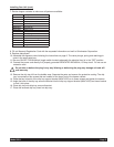
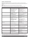
7. Review hopper contents to make sure all parts are available:
8. Fill out Warranty Registration Card with the requested information and mail to Grindmaster Corporation.
9. Replace side panels.
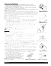
10. Assemble the dispense valve following the instructions on page 9. The valve plunger, spring and retaining pin
come in the small parts bag.
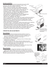
11. Be sure ON-OFF-CLEAN switch (toggle switch located underneath the electrical box) is in the “OFF” position.
12. Connect the power cord directly to a properly grounded DEDICATED 220V/60Hz, 15 Amp circuit. Do not use an
extension cord.
Do not alter or deform the plug in any way! Altering or deforming the plug may damage unit and will
void warranty.
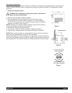
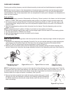
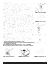
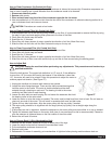
13. Remove the drip tray kit from the bubble wrap. Separate the parts and remove the protective coating. The drip
tray is mounted on two screws that are located on the lower front of the freezer cabinet.
14. Place the key hole slot of the drip tray support bracket (W0471022) on to these screws and tighten the screws.
15. Angle the back of the drip tray surround bracket into the drip tray support bracket (W0471022) and lower bracket
to lock it into place.
16. Place drip tray onto drip tray surround bracket.
17. Place the louvered drip tray insert into drip tray.
!
Part # Description
W0600114 Manual
W0600073 Rubber Pad Sheet
W0600121 Merchandiser Installation Sheet
W0600012 MSDS Sanitizer Sheet
W0600159 Warranty Registration Card
W0890218 Drip Tray Kit
W0520094 Hopper Cover
W0480445 Valve Handle
W0631230 Valve Spring
*
Carb Tube
*
Dispense Valve Plunger
W0470076 Lubricant
W0631903 Sanitizer Packets
W0340022 O-rings
* Optional items specified when the unit is ordered.
Model 3511 Page 5