


Page 16 Crathco
®
5000 Series Manual
Cleaning Following Complete Disassembly of Unit (cont.)
IMPORTANT: After disassembly, thoroughly scour each part of the freezer in a warm mild detergent
solution including the inside of the freezing cylinder and the mix storage hopper. Rinse each part with
clear water. Prepare a minimum of 3-1/2 gallons (13 liters) of sanitizing solution (Divorsol CX or equiva-
lent) following the manufacturer's instructions.
Note: Add 3 ounces (85.4 mg) of Divorsol CX to 3-1/2 gallons (13
liters) of 120° Fahrenheit (50° Centigrade) water to achieve a
concentration of 200 parts per million. Dip or wipe each part
in sanitizing solution and allow them to dry on clean paper toweling.
Reassembly
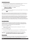
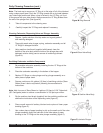
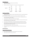
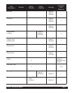
1. Wet the inner rubber lip of the rotary portion of the seal and the
back end of the auger shaft with water. Slide rotary portion of
assembly onto the auger shaft, RUBBER FIRST, with the smooth
sealing surface toward the back of the auger. (See Figure Z)
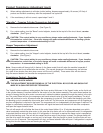
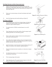
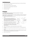
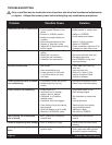
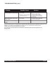
2. Insert the stationary portion of the seal into the grooved rubber boot with
the polished surface facing out (forward). Lubricate the grooved exterior
portion of the boot and insert it straight back into recess at the
back of the freezing cylinder, RUBBER FIRST.
(See Figure AA & BB)
Note: If the circular portion of the seal is white, make sure that the
groove is toward the rubber (back of freezer).
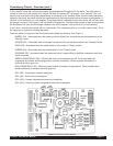
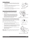
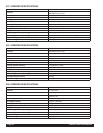
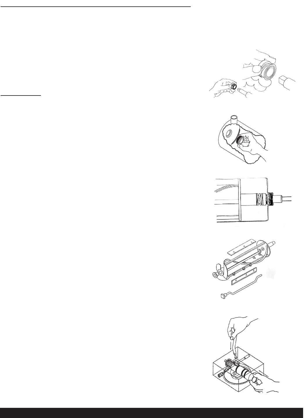
3. Reassemble the dasher assembly, as shown in Figure CC. Insert
the larger front and smaller rear white plastic bearings into
dasher, then slip in the stator rod. Attach scraper blades.
Carefully and slowly guide the auger into the freezing cylinder
taking care not to damage the seal assembly. Turn auger shaft
until it engages the square drive coupling.
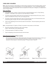
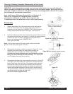
4. Reassemble the dispensing valve assembly as shown in Figure DD.
Thoroughly wash and sanitize all components, lubricate the inside
bore of valve body with a thin film of food grade sanitary lubricant.
Reinstall the O-Rings on the plunger assembly and lubricate the
entire plunger. Reassemble the valve and replace the retainer pin.
Inspect and lubricate the large O-Ring and refit it into the rear of
the valve assembly. Install the valve assembly on the front studs
and tighten knobs until they are finger tight.
Do not use tools to tighten knobs.
Figure Z Reassemble rotary
portion of seal as shown
Figure AA Installing the stationary
portion seal
Figure CC
Figure DD
Figure BB Seal Assembly installed correctly