


LIQUID COFFEE DISPENSERS
LCD2-1 & LCD2-3
OPERATIONS MANUAL
INSTALLATION
WATER INLET CONNECTION
The following is required for water hook-up:
• A quick disconnect water connection or enough coiled tubing so the machine can be moved for cleaning underneath. (required for NSF
approved water hook-up)
• A 1/4" male flare adapter is provided (packed inside the drain tray) to be attached by the installer to the back of the machine for hook-up
to water supply.
• Installation to a water filter system is required to prevent lime and scale build up in the machine.
• Water pipe connections and fixtures directly connected to potable water supply shall be sized, installed, and maintained in accordance
with Federal, State, and Local codes. (required for NSF approved water hook-up)
• Equipment is to be installed with adequate backflow protection to comply with applicable Federal, State, and local codes. (required for
NSF approved water hook-up)
WATER HOOK-UP
1. Install the (2) front 4" legs to provide approximately 1/2" clearance with the bottom of the machine.
2. Install drain tray bracket to the front of the machine by sliding the bracket between the front 4" legs and the bottom of the machine.
The bracket should self locate with screw heads on the bottom of the machine. Tighten the front 4" legs to secure the drain tray bracket.
3. Install the (2) back 4" legs and tighten.
4. Install the plastic drain tray onto the drain tray bracket. (Note: The drain tray is provided with a removable plug to allow for plumbing the
drain tray to a drain.)
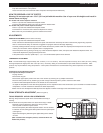
5. Connect a flexible water supply hose to 3/8-18 NPT connector in rear. Ensure the water supply hose has sufficient length to allow the
machine to be moved for cleaning or service. Supplying hot water to the machine will greatly increase the capacity of the machine. The
use of copper tubing is required to prevent rupture when using a hot water supply. A maximum inlet water temperature of 120° F is
recommended.
6. Ensure that the water supply to the machine is with 20 to 100psi. Install a pressure regulator if pressure is too high.
ELECTRICAL HOOK-UP
Ensure water connection is made to machine before proceeding
The electrical ratings for your dispenser are located on the serial plate on the outside cabinet. For configuration of three heater models to
optional wattages, refer to configuration manual 62210 supplied with the machine.
1. For cord connected models, plug the power cord into an appropriate grounded and dedicated electrical outlet. Go to step 8.
2. For hard-wired models not supplied with a can electrical cord, the dispenser should be connected to a dedicated circuit with a fused
disconnect switch or a circuit breaker near the dispenser.
3. Strain relief knockouts are supplied on the back of the machine chassis for power entry.
• Electrical connections and wiring materials must conform to local codes and/or be in compliance with the National Electric Code
• Use only copper conductors
4. Remove the access panel located on the upper left side of the dispenser. Note: wiring diagram is on backside of access panel.
5. Connect the power supply conductors, neutral and ground wire to the appropriate positions on the terminal block located on the upper
left side of the dispenser. The ground lug is separate from the terminal block. Note: if power supply available does not provide for a
neutral conductor, a stepdown transformer must be installed to provide the necessary 120 volt power supply for the control circuits.
Consult factory for assistance.
6. Install the side access panel.
7. Flip power supply to machine “ON” at the branch supply disconnect.
8. Flip power switch to the “ON” position and allow the water tank to fill. The machine will make a subtle hissing sound while filling. Allow
3-4 minutes for fill time depending on water pressure.
9. After the water tank has completed the fill cycle, the green Ready light located on the front of the dispenser should extinguish signifying
that the heating element has been activated. Allow 10-60 minutes for the Ready light to illuminate signifying the water tank has
reached operating temperature. (Note: Heatup time is dependent on water inlet temperature and input wattage to the machine.)
Attention: This machine employs an interlock switch to disable the dispense and fill circuits when the front door is open. Ensure the front
door is closed while installing or operating the machine. A watchdog circuit also monitors the water level in the tank and will disable the
machine if the water level in the tank is not normal within (5) minutes of fill time. The machine will require power to be reset to clear the
watchdog timeout.
BAG-IN-BOX HOOK-UP
• Place bag-in-box containers inside the cabinet behind the front door. Connect the quick connect fitting to each bag-in-box.
• After connecting the bag-in-box, flip the water switch located behind the front door to the “OFF” position and flip the concentrate switch to
the “ON” position.
• Activate the appropriate dispense switch on the front of the door in order to prime the concentrate lines with product. Continue to activate
the dispense switch until concentrate is dispensed from the appropriate dispense spout.
• Repeat steps for other dispense spout.