5
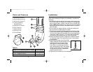
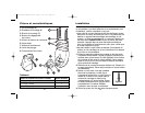
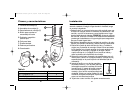
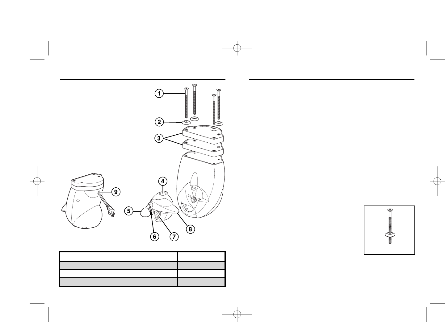
1. Mounting Screws (4)
2. Mounting Washers (4)
3. Mounting Spacers (2)
4. Cutting Assembly
Release Button
5. Magnetic Lid Holder
6. Can Guide Pin
7. Geared Wheel
8. Piercing Lever
9. Cord Storage
4
Parts and Features Installation
This can opener is designed to be installed under a cabinet or
shelf. When selecting a location for installation, consider the
following:
• An electrical outlet should be within easy reach of the plug
so the cord does not drape over a heating or cooking appli-
ance, a sink or basin, or get in the way of your normal work
space. HINT: Before drilling any holes, plug unit into desired
outlet and hold can opener in proposed location to ensure
cord will reach.
• Do not install can opener above a cooking or heating unit,
such as a stove, or above a sink or basin.
1. Remove the mounting template page from the back of the
Use & Care booklet. Align the dashed line on the template
with the front edge of the top side of the mounting surface
and tape in place. Drill four
3
⁄16” (5 mm) holes as indicated
and remove the template from the mounting surface.
2. Select the desired number of spacers to use (see Table A
on previous page). Place spacer(s) on top of can opener
(if applicable).
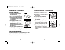
3. Insert screw through one of the white
plastic washers with the flat side of the
washer away from the screw head
(see Figure 1). Insert screw through
hole drilled in mounting surface and
into corresponding hole in can opener.
Tighten several turns. Do not tighten
all the way at this time. Repeat with
remaining three screws.
4. Tighten all four screws. Do not overtighten.
Figure 1
Height of Front Overhang (Cabinet or Shelf) Spacers Needed
0 to
1
⁄2 inch (1 cm)
0
1
⁄2 to 1
1
⁄4 inches (1 to 3 cm)
1
more than
1
1
⁄4
inches (3 cm)
2
Table A
840123500 ENv03.qxd 2/19/04 4:59 PM Page 4


