


– 6 –
INSTALLATION CODES AND STANDARDS
Your Hobart griddle should be installed in accordance with:
In the United States
1. State and local codes.
2. National Electrical Code ANSI/NFPA 70 (latest edition).
In Canada:
1. Local codes.
2. Canadian Electrical Code Part 1 CSA-C22.1 (latest edition).
ELECTRICAL CONNECTIONS
WARNING: ELECTRICAL AND GROUNDING CONNECTIONS MUST COMPLY WITH THE APPLICABLE
PORTIONS OF THE NATIONAL ELECTRICAL CODE AND/OR OTHER LOCAL ELECTRICAL CODES.
WARNING: DISCONNECT ELECTRICAL SUPPLY AND PLACE A TAG AT THE DISCONNECT SWITCH TO
INDICATE THAT YOU ARE WORKING ON THE CIRCUIT.
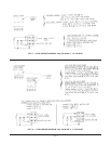
Standard Electrical Connections
1. Remove the small cover plate on the back of the griddle. This exposes the built-in terminal box and line leads.
2. Select a suitable knockout on the rear or bottom of the terminal box.
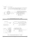
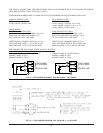
3. Connect the line leads to the supply wires (refer to the wiring diagram).
4. Push the excess wire into the terminal box and replace the cover plate.
Close Back Wall, Rigid Conduit Electrical Connections
If the griddle is to be installed close to a back wall and rigid condit is to be used, follow this procedure:
1. Lift front of griddle top only as far as necessary to gain access to the terminal box on the body's inside rear.
2. Prop the griddle top up securely to prevent it from falling down and causing serious hand injury. Do not lift
the griddle top too high as the thermostat and griddle terminals may be damaged.
3. Remove the fastener near the bottom of the terminal box and slide the enclosure up to expose knockouts.
4. Connect griddle's line leads to the supply wires, as shown in the applicable wiring diagram. Do not disturb
the griddle's wiring.
5. Slide enclosure down and secure it with fastener.
6. Lower the griddle top. Make sure that it is securely in place.
Since the griddle is not fused, you must connect it to a fused circuit equipped with a suitable disconnecting means
as required by local authorities.