


701 S Ridge Avenue, Troy, OH 45374
1-888-4HOBART • www.hobartcorp.com
Page 2 of 2 F-39964 – HO851G Revolving Tray Oven - Gas
As continued product improvement is a policy of Hobart, specications are subject to change without notice.
HO851G REVOLVING
TRAY OVEN - GAS
F-39964 (REV. 08/08) LITHO IN U.S.A. (H-01)
SPECIFICATIONS:
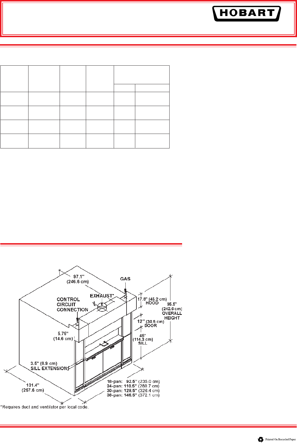
DETAILS AND DIMENSIONS
Gas – 1" NPT pipe size; Standard – Natural Gas @
5"-14" w.c.; Optional – Propane Gas @ 13"-14" w.c.
Must not exceed 14" w.c.
Electrical – 120V/60Hz/1 PH. Oven control: 12.0
amps.
Oven provided relay with 120V output for fan opera-
tion, 4.0 amp max
1
⁄6 H.P.
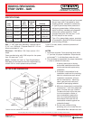
Hood – Suitable for Type I or Type II applications.
See table for duct size and fan cfm requirement by
model. 0.6"w.c. static pressure drop at hood.
NATURAL
GAS PROPANE
WGT MAX. GAS
VENTING
(LBS) CAPACITY BTU/HR BTU/HR CFM DUCT. DIA.
5121 8"
(2323 kg)
18-PAN
250,000 200,000
700
(20.3 cm)
5812 10"
(2636 kg)
24-PAN
300,000 250,000
900
(25.4 cm)
6429 10"
(2916 kg)
30-PAN
300,000 250,000
1200
(25.4 cm)
7122 10"
(3231 kg)
36-PAN
350,000 300,000
1400
(25.4 cm)
Customer to supply duct and roof mounted
fan per local code. If accepted by local
building ofcials, suitable for connection
to Type B pipe except when products of
baking are grease laden. Airow proving
switch is factory installed and integrated
with burner system operation. Oven
provided relay with 4.0 amp max
1
/6 H.P.
@ 120V output for fan control.
Type I: For grease laden vapors, products
of combustion. (See NFPA 96 and consult
local building ofcials.)
Type II: For heat, steam, odors and products of
combustion.
NOTES
1. Level oor required. Floor should be level within
1
/8" per foot for proper installation. Slope should
not exceed
3
/4" in all directions under the unit.
2. The purchaser is responsible for proper installation
in order to validate the warranty.
A factory technician or factory
authorized installation technician
must supervise and approve any
installation.
3. Purchaser is responsible for all
installation costs and for providing:
labor to unload oven upon arrival;
installation mechanics; all local
service connections - electricity,
vents, gas per local code; and
disposal of packaging material.
4. Minimum clearances to combustible
construction: 1 inch from sides and
back, 3 inches from top. Caution:
To reduce the risk of re, the oven
is to be mounted on oors of
non-combustible construction
with non-combustible ooring
and surface nish and with no
combustible material against the
underside thereof.
5. Do not route utilities (wiring,
plumbing, etc.) in or under the non-
combustible oor beneath the oven.