


– 4 –
INSTALLATION
Immediately after unpacking the mixer-grinder, check for possible shipping damage. If the machine
is found to be damaged, save the packaging material and contact the carrier within 15 days of delivery.
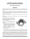
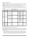
Prior to installation, test the electrical service to make sure it agrees with the specifications on the
machine data plate (Fig. 5).
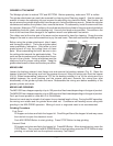
CASTER SETS AND / OR ADJUSTABLE LEG SETS
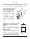
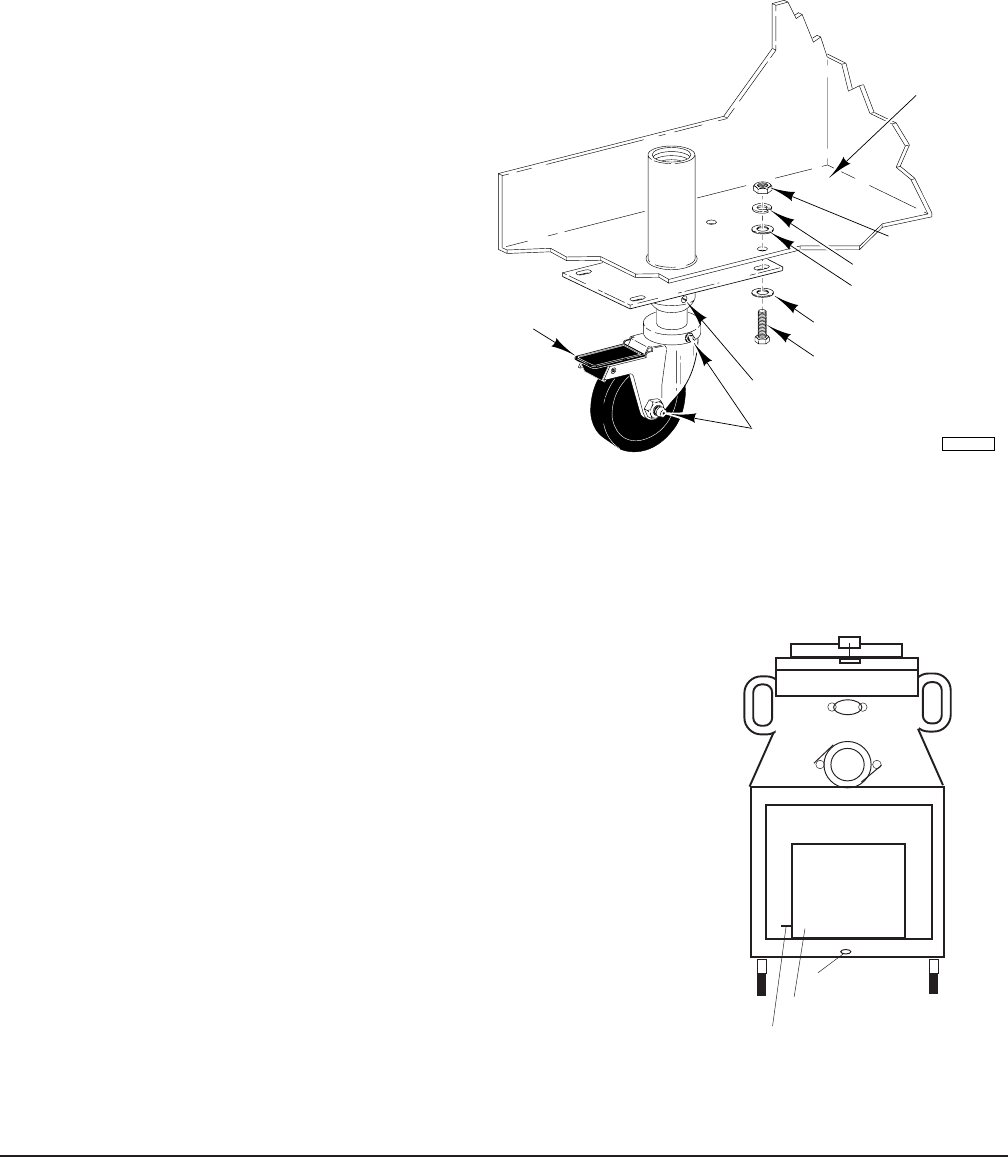
With the mixer-grinder securely elevated using
the base frame for support, bolt the caster
assemblies through the corner holes using four
hex-head
5
/16-18 bolts, lockwashers, washers,
and nuts for each caster, provided.
• When equippped with two Fixed and two
Swivel casters, install Fixed Casters-
without-Brake on rear corners of the
machine and Swivel Casters-with-Brake
on front corners.
• On machines with four identical legs or
casters, install one on each corner.
All casters and leg sets use washers under the
flange and above the machine base frame.
Insert bolt up through the flange from the bottom
with the lockwasher next to the nut on top
(Fig. 2).
LEVELING
Level the mixer-grinder, both front-to-back and side-to-side, by
loosening the two set screws on the caster shaft (Fig. 2) and screwing
the caster up or down. Tighten both set screws when level.
LUBRICATION
The mixer-grinder is shipped with oil already installed. If oil loss is
observed, the oil levels of both transmissions should be checked prior
to operation. Contact Hobart Service.
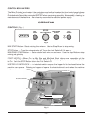
PNEUMATIC FOOT SWITCH
To install the pneumatic foot switch, remove the lower front panel
(6 screws). Remove the knockout from the bottom front floor panel
inside the machine compartment (Fig. 3) and insert the tube from the
foot switch through the knockout hole. Remove the cap from the
barbed fitting at the bottom left side of the control box (Fig. 3) and
connect the tube from the pneumatic foot switch onto the barbed
fitting using the clamp provided. A pliers will be needed to squeeze the
clamp open during installation. Avoid kinking the tube.
NUT
MACHINE
BASE FRAME
LOCKWASHER
WASHER
WASHER
BOLT
BRAKE
GREASE FITTING
SET SCREW
PL-52464
Fig. 2
Fig. 3
KNOCKOUT
BARBED FITTING
CONTROL BOX