


F74C REVERSE RINSING FILTER; MV876 AUTOMATIC-BACKWASH CONTROLS
62-3061 4
PLANNING THE INSTALLATION
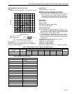
The F74C should be sized based on the required flow rate
and the resulting pressure drop across the filter. As a
guideline for most applications, the F74C should be sized for
a pressure drop between 3 psi and 7 psi.
EXAMPLE: What size F74C is required to provide a flow rate
of 20 gpm? Reading Table 2 at 4 psi pressure drop, a 1 in.
filter can provide 20.2 gpm without exceeding 4 psi pressure
drop.
An increased pressure drop across the filter results when
higher velocities are maintained to increase the capacity
through any given size filter. Severe pressure drops will be
encountered as capacity approaches that of the pipe size. To
ensure the backwash cycle operates properly and cleaning
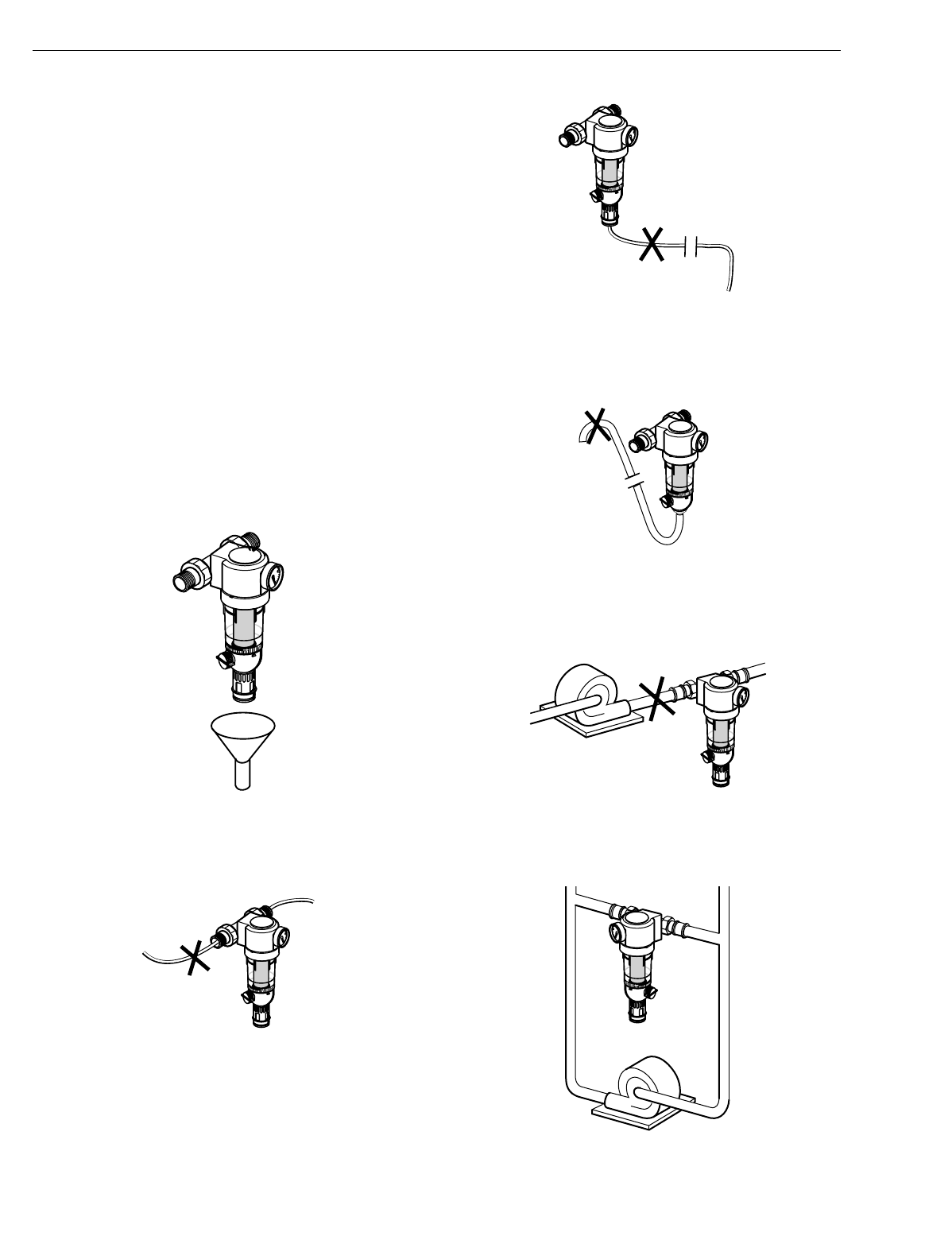
action is not reduced, follow all recommendations in Fig. 3.
Refer to Fig. 3a for an ideal installation.
NOTE: All filter installations are different. The size, type and
amount of dirt and debris and the flow rate must
always be considered when choosing a screen and
deciding to install multiple F74C Water Filters in
parallel.
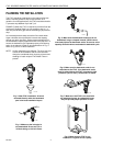
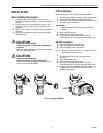
Fig. 3. Ideal F74C installation. A funnel
mounted directly under the backwash
port is the best installation layout.
Fig. 4. Make sure the inlet pipe is
not downsized. Do not use 1/4 or
3/8 inch tubing on 3/4 inch filters.
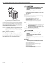
Fig. 5. Make sure the backwash outlet pipe is not
downsized, long or crimped. Instead, install a short
oversized pipe on the backwash outlet. Do not use a low
capacity solenoid valve to automate the backwash cycle.
Fig. 6. Make sure the backwash outlet is not
raised above the F74C. If the backwash outlet
must be raised above the F74C, increase the inlet
pressure 5 psi for every 10 feet that it is raised.
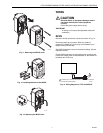
Fig. 7. Make sure the F74C is not used with
an undersized pump. An undersized pump
may not provide proper pressure or flow.
Fig. 8. Make sure the F74C is not
installed in a bypass across a pump.
M17705
M17706
M17707
M17708
M17709
M17704