


24
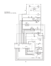
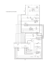
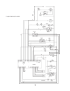
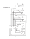
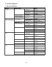
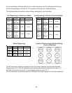
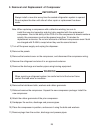
If you experience problems with the ice or water dispense, use the following charts along
with the wiring diagram (section III, 3) to guide you through your troubleshooting.
The following tables show the proper voltage readings for each operation.
Water Dispensing
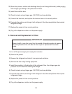
Ice Dispensing in Continuous Mode
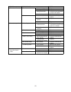
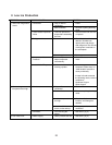
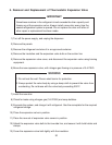
Ice Dispensing in Portion Controlled Mode
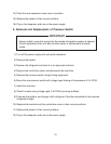
Layout of Portion Control Switch Wiring
(Front of Machine)
Lead 1 Lead 2 Dispense Non-Dispense
K2 PIN 6
(LBU)
to GND
or
NEUTRAL
120 VAC 0 VAC
K5 PIN 4
(W/O)
or
(RED) on
sensor
to K5 PIN 5 (Y)
or
(WH) on
sensor
5 VDC 0 VDC
K5 PIN 4
(W/O)
or
(RED) on
sensor
to K5 PIN 6
(W/BR)
or
(BK) on
sensor
5 VDC 5 VDC
Lead 1 Lead 2 Dispense Non-Dispense
K2 PIN 8
(DBU)
to K4 PIN 2
(LBU)
24 VAC 0 VAC
K5 PIN 7
(RED)
to K5 PIN 9
(BK)
5 VDC 5 VDC
K5 PIN 7
(RED)
to K5 PIN 8
(WH)
5 VDC 0 VDC
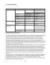
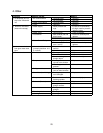
The K2 connector supplies voltage to the ice and water dispense motors and solenoids
through pins 4, 6, 8. The K2 connector also has the gear motor protect circuit on pins 1, 2
the flush valve circuit on pins 9, 10 and voltage inputs on pins 3, 5, 7.
The K5 connector is used exclusively for the input and output signals for the optical sensors.
Lead 1 Lead 2 Dispense Non-Dispense
K2 PIN 6
(LBU)
to GND
or
NEUTRAL
120 VAC 0 VAC
K5 PIN 1
(W/R)
or
(RED) on
sensor
to K5 PIN 3
(W/BK)
or
(BK) on
sensor
5 VDC 5 VDC
K5 PIN 1
(W/R)
or
(RED) on
sensor
to K5 PIN 2
(W/BL)
or
(WH) on
sensor
5 VDC 0 VDC