


54
VI. REMOVAL AND REPLACEMENT OF COMPONENTS
1. SERVICE FOR REFRIGERANT LINES
[a] REFRIGERANT RECOVERY [EXCEPT F-1000MLF(-C)]
The icemaker unit is provided with two Refrigerant Access Valves - one on the low-side
and one on the high-side line. Using proper refrigerant practices recover the refrigerant
from the Access Valves and store it in an approved container. Do not discharge the refrig-
erant into the atmosphere.
[b] REFRIGERANT RECOVERY [F-1000MLF ONLY]
The refrigerant charge on the F-1000MLF is provided from the external Compressor Rack
Assembly. In the event that service is required on the F-1000MLF, close the Suction and
Liquid Line Shut-off Valves located at the rear of the unit. Attach the Service Manifold
Hoses to the High-side, Low-side and Evaporator Pressure Regulator (E.P.R.) access ports
to purge or evacuate the unit. To recharge the system, simply open the Suction and Liquid
Line Shut-off Valves after evacuating the F-1000MLF.
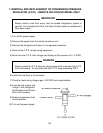
[c] EVACUATION AND RECHARGE [R-404A]
1) Attach Charging Hoses, a Service Manifold and a Vacuum Pump to the system. Be
sure to connect Charging Hoses to both High-side and Low-side Access Valves.
IMPORTANT
The vacuum level and vacuum pump may be the same as those for current
refrigerants. However, the rubber hose and gauge manifold to be used for
evacuation and refrigerant charge should be exclusively for POE oils.
IMPORTANT
Ensure all components, fasteners and thumbscrews are securely in place
after the equipment is serviced.
IMPORTANT
1. The Polyol Ester (POE) oils used in R-404A units can absorb moisture
quickly. Therefore it is important to prevent moisture from entering the
system when replacing or servicing parts.
2. Always install a new filter drier every time the sealed refrigeration sys-
tem is opened.
3. Do not leave the system open for longer than 15 minutes when replac-
ing or servicing parts.