


22
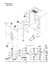
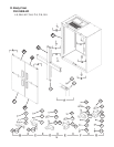
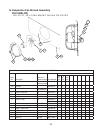
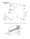
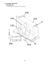
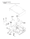
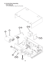
Installation Instructions for Parts 10, 11, 12, & 13
1. The original heat shield must be removed. This can be done by lifting the evaporator up and
sliding the heat shield out.
2. The new heat shield (part #13) is then installed in the rotocast drain pan.
3. The clips are then slid onto the end plate on the evaporator. Support clips (part #12) are
installed onto the hairpin end of the evaporator as shown in the illustration.
4. The other support clips (parts #10 and #11) are installed on the return bend end (same side
as inlet andoutlet tubes) as shown in the illustration.
NOTE: All clips are shown in the illustration in the correct orientation for installation. The
parts are slid onto the evaporator bracket using the tab on the support clip.
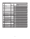
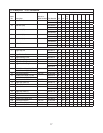
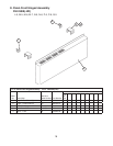
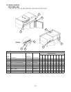
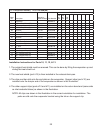
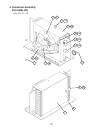
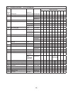
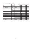
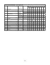
Title: H. Evaporator Assembly Model: FH2-SSB(-HD)
Index
No. Description
Material or
Model Number Part Number
Required Number
H-0
to
M-5
M-6
to
P-5
P-6
Q-5
1 Evaporator - 2A0636-01 1 1 1
2 Bracket-Evap Shroud(R) SS 4A0545-01 1 1 -
2a T2 Screw
4×8, SS 7P32-0408 2 2 -
3 Bracket-Evap Shroud(L) SS 4A0548-01 1 1 -
3a T2 Screw 4×8, SS 7P32-0408 2 2 -
4 Heater – Defrost - 3A0591-01 1 1 1
5 Thermostat – Defrost - 4A0954-02 1 1 1
5a T2 Screw 4×8, SS 7P32-0408 2 2 2
6 Bushing - 420470-01 1 1 1
7 Thermistor – Defrost - 4A1428-01 1 1 1
7a Thermistor – Clip - 320418-01 1 1 1
8 “Y” Joint - 4A1687-03 1 1 1
9 “Y” Joint - 4A1687-02 1 1 1
10 Clip – Support Evap (A) - 4A2826-01 1 1
11 Clip – Support Evap (B) - 4A2827-01 1 1
12
Clip – Support Evap (C) - 4A2828-01 2 2
13 Shield – Heat - 3A1853G01 1 1