


21
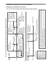
5) Initial Harvest Cycle – LEDs 1, 4, and 2 are on. WV continues. Comp, FMR, and
HGV energize. CB monitors the warming of the evaporator via the thermistor located
on the suction line. When the thermistor reaches 48°F (9°C), CB reads 3.9 kΩ from the
thermistor and turns harvest termination over to the harvest timer (S4 dip switch 1 & 2).
The harvest timer has settings of 60, 90, 120, and 180sec. Thepump-out timer (S4dip
switch 3 & 4) acts in place of the harvest timer during cycles with a pump-out (S4 dip
switch 5 & 6). WV remains energized during harvest for a maximum of 6min. or the
length of harvest, whichever is shorter.
a) Comp Diagnosis: Check that evaporator is warming. Ifnot, conrm that Comp
energizes. If not, check for 115VAC at CB K1 #1 or #9 (V) to neutral (W). If 115VAC
is not present, check for 115VAC at CB K1 #7 or #10 (BR) to neutral (W). If115VAC
is present at CB #7 or #10 (BR) and not at CB #1 or #9 (V), replace CB. If 115VAC
is present, check for 115VAC at MC solenoid. If 115VAC is present, conrm contacts
are closed. If not, replace MC. If MC contacts are closed, check Comp start and run
capacitors, Comp start relay, and Comp motor winding.
b) HGV Diagnosis: If Comp is energized and evaporator is not warming, check that
HGV energizes and opens. Check for 115VAC at CB K1 #2 (P) to neutral (W).
If115VAC is not present, replace CB. If 115VAC is present, check for 115VAC at HGV
coil and check HGV coil continuity. Replace as needed.
c) LLV Diagnosis: Conrm that LLV is de-energized and closed (not bypassing).
Ifenergized, replace CB. If de-energized and bypassing, replace LLV.
d) WRV Diagnosis: Conrm WRV is not leaking by.
e) Initial Harvest Cycle Termination Diagnosis: When the thermistor reaches 48°F
(9°C), CB reads 3.9 kΩ from the thermistor and turns harvest termination over to
the harvest timer (S4 dip switch 1 & 2). Check discharge line temperature. For a
thermistor check, see "II.F.Thermistor Check." If 1-min. ll cycle starts after harvest
timer terminates, check that FS is clean and operating properly. See "II.E. Float
Switch Check and Cleaning." If FS is closed, CB proceeds to the next cycle. Ifnot,
replace CB.
Note: The min. total time allowed by CB for a complete harvest cycle is 2 min.
Max. harvest time allowed is 20 min.
NOTICE! On models with "G" control board and no harvest pump timer relays,
S4dip switch 7 must remain off. Otherwise, PM energizes in reverse direction the
last 50 seconds of harvest and empties water from water tank.
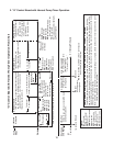
6) Freeze Cycle – LED 1 is on. Comp and FMR continue. PM, FM, and LLVenergize.
WV and HGV de-energize. Appliance is held in freeze by a 5-min. short cycle protection
timer. After 5-min. timer terminates and FSopens, freeze cycle terminates.
a) Freeze Cycle Diagnosis: Conrm Comp and FMR continue. Conrm that PM, FM,
and LLV energize. Conrm WRV opens. Next, conrm WV and HGV de-energize.
During the rst 5 min. of freeze, conrm evaporator is cooling. If not, conrm
WV de-energized (not leaking by), HGV de-energized (not bypassing), LLV and
FM energize, TXV and HM operate correctly, WRV opens, Comp is efficient, and
refrigerant charge is correct. See "VIII.A. Specication and Performance Data."