


42
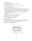
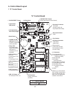
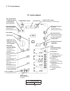
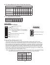
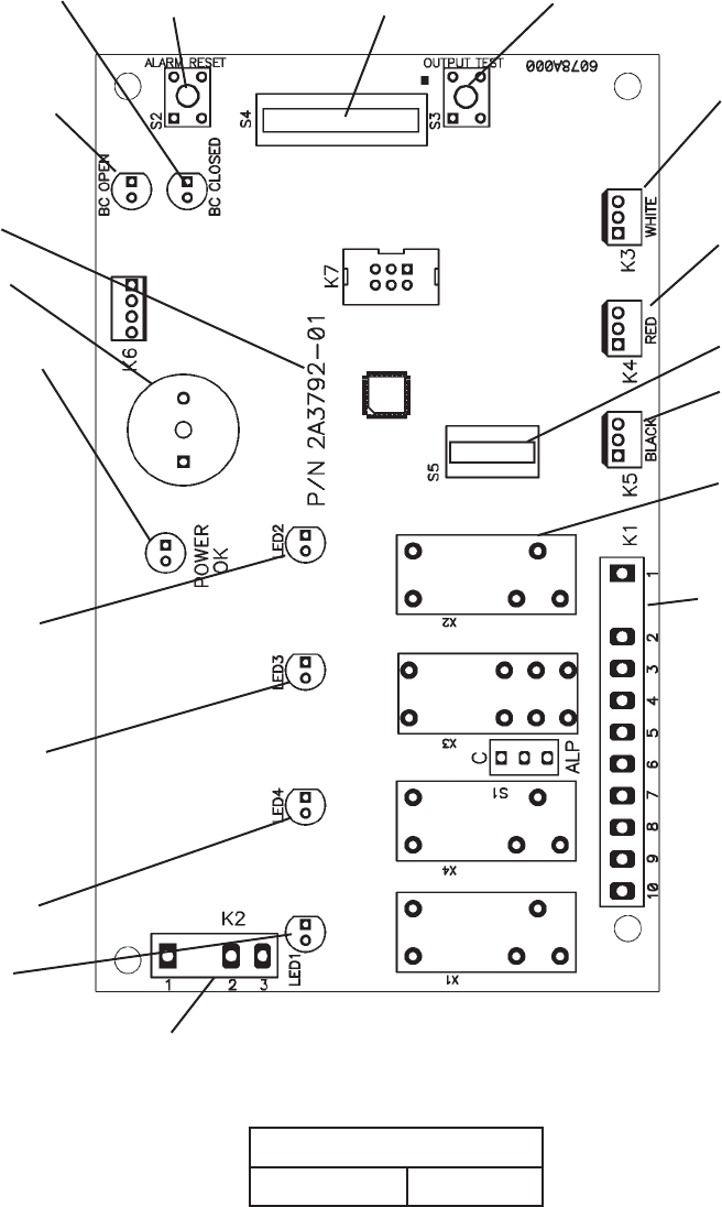
2. "G" Control Board
"G" Control Board
Part Number 2A3792-01
"G" Control Board
• K4 (red) Connector
Mechanical Bin Control or
K4 Jumper (thermostatic
bin control application)
Label
(control board revision
level indicated on label
on side of relay)
• K1 Connector
Pins #1 through #10
#1, 9 Magnetic Contactor or
Compressor Relay
#2 Hot Gas Valve
#3 Fan Motor
Liquid Line Valve
#4 Pump Motor (icemaking)
#5 Pump Motor
(harvest pump timer and
pump-out)
#6 Inlet Water Valve
#7, 10 Component Power
Supply
#8 Open
• Bin Control Switch
Open LED (yellow)
(mechanical bin
control application only)
• Bin Control Switch
Closed LED (green)
(on continuously
in thermostatic bin
control application)
• LED 2 (X2 Relay)
LED 2 on:
K1 Connector Pin #2
LED 2 off:
K1 Connector Pin #3
• LED 3 (X3 Relay)
LED 3 on:
K1 Connector Pin #5
LED 3 off:
K1 Connector Pin #4
(energized in freeze)
• LED 4 (X4 Relay)
K1 Connector Pin #6
• LED 1 (X1 Relay)
K1 Connector Pin #1, #9
• K2 Connector
Control Transformer
(10.5VAC)
• S5 Dip Switch
• "ALARM RESET" Button
• S4 Dip Switch
• "OUTPUT TEST" Button
(used to test relays on control board)
• K3 (white) Connector
Thermistor
(harvest control and
high temperature safety)
• K5 (black) Connector
Float Switch
(water level)
• Part Number
• Alarm Buzzer
• Relay LEDs
(4) (indicate which
relays are energized
and which K1
connector pins are
energized
• POWER OK LED
(red) (lights when
10.5VAC is supplied
to K2 connector)