


6
Consult the designs in the front pages referenced in the text by
alphabet letters. Closely follow the instructions set out in this
manual. All responsibility, for any eventual inconveniences, damages
or fires caused by not complying with the instructions in this manual,
is declined.
The cooker hood must be placed at a minimum distance of 50 cm from
the cooking plane for electric cookers and 65cm for gas or mixed
cookers.
If the appliance is installed above a gas cooking device with installation
instructions specifying a greater clearance, you must take this into
account.
Do not tile, grout or silicone this appliance to the wall. Surface
mounting only.
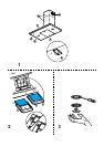
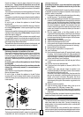
The hood is equipped with a top air outlet B for discharge of fumes to
the outside (Ducting version exhaust pipe and pipe fixing clamps
not provided).
Should it not be possible to discharge cooking fumes and vapour to the
outside, the hood can be used in the filter version, fitting an activated
carbon filter and the deflector F
on the support (bracket) G, fumes and vapours are recycled through
the top grille H by means of an exhaust pipe connected to the top air
outlet B and the connection ring mounted on the deflector F (exhaust
pipe and pipe fixing clamps not provided).
The models with no suction motor only operate in ducting mode, and
must be connected to an external suction device (not supplied).
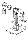
Installation - Fig. 4
Preliminary information for installation of the hood:
Disconnect the hood during electrical connection, by turning the home
mains switch off. Expansion wall plugs are provided to secure the
hood to most types of walls/ceilings. However, a qualified technician
must verify suitability of the materials in accordance with the type of
wall/ceiling. The wall/ceiling must be strong enough to take the weight
of the hood.
Do not tile, grout or silicone this appliance to the wall. Surface
mounting only.
Do not fix chimney flue to furniture or fly over shelves unless the
chimney flue can be easily removed, in case maintenance is
ever required.
Where foreseen remove the grease collecting panels.
Remove the grease filter/s
Do not tile, grout or silicone this appliance to the wall. Surface
mounting only. Do not fix chimney flue to furniture or fly over shelves
unless the chimney flue can be easily removed, in case maintenance
is ever required.
=
=
X
X
H
=
=
X
F
F
G
G
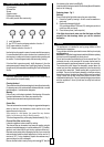
Assembling the chimney flue support/bracket (3 parts):
The three parts should be fixed with 4 screws, the support extension
is adjustable and should correspond to the internal width of the
telescopic chimney flue.
Assembling the deflector (only when a deflector composed of
3 parts is supplied the deflector should be only for the filter
version):
The three parts should be fixed with 2 screws, the deflector extension
is adjustable and should correspond to the width of the chimney flue
support, to which it is then fixed.
1. Using a pencil, draw a line on the wall, extending up to the ceiling,
to mark the centre. This will facilitate installation.
2. Rest the drilling template against the wall: the vertical centre line
printed on the drilling template must correspond to the centre line
drawn on the wall, and the bottom edge of the drilling template
must correspond to the bottom edge of the hood: bear in mind
that, when installation is complete, the underside of the hood
must be at least 50 cm above the cooker top in the case of electric
cookers, and at least 65 cm above the cooker top in the case of
gas or mixed cookers.
3. Rest the support bracket on the drilling template so that it
coincides with the dotted rectangle, mark the two outer holes and
drill them, remove the drilling template, insert 2 wall plugs and fix
the hood support bracket into place using two 5x45mm screws.
4. Hang the hood on the bracket.
5. Adjust the distance of the hood from the wall.
6. Adjust the horizontal position of the hood.
7. Using a pencil mark the cooker hood permanent drill hole inside
the suction group (two drill holes are necessary for fastening).
8. Remove the hood from the bracket.
9. Drill at the point marked (Ø8mm - see operation 7).
10. Insert 2 wall plugs.
11. Rest the chimney support bracket G against the wall, touching
the ceiling. Use the support bracket as a drilling template (the
small slot formed on the support must coincide with the line drawn
on the wall as above operation 1) and mark 2 holes with a pencil,
drill the holes (Ø8mm), insert 2 wall plugs.
12. Fix the chimney support bracket to the wall using two 5x45mm
screws.
13. Hook the hood onto the bottom bracket.
14. Fix the hood into its final position on the wall (ABSOLUTELY
ESSENTIAL).
15. Connect a pipe (pipe and pipe clamps not provided, to be
purchased separately) for discharge of fumes to the connection
ring located over the suction motor unit.
If the hood is to be used in ducting version, the other end of the
pipe must be connected to a device expelling the fumes to the
outside. If the hood is to be used in filter version, then fix the
deflector F to the chimney support bracket G and connect the
other extremity of the pipe to the connection ring placed on the
deflector F.
16. Make the electrical connections.
17. Apply the chimney stacks and fasten them at the top to the
chimney support G (17b) using 2 screws (17a).
18. Slide the bottom section of the chimney down until it completely
covers the suction unit and slots into the housing provided on top
of the hood.
Replace the grease filter/s (and where foreseen the grease collecting
panels) and check that the hood is operating correctly.
Electrical connection
The electrical tension must correspond to the tension noted on the
label placed inside the cooker hood. Connect the electrical plug,
where provided, to the an easily accessible outlet in conformity with
local standards in force.
Where an electrical plug is not provided (for direct connection to
electrical network) place a standards approved bipolar switch with an
aperture distance of not less than 3mm (accessible) from the contacts.