


UK
! It is important to conserve this booklet for
consultation at any moment. In the case of sale,
cession or move, make sure it is together with the
product.
! Read the instructions carefully: there is important
information about installation, use and safety.
! Do not carry out electrical or mechanical variations
on the product or on the discharge conduits.
Installation
Electric connection
! The power tension must correspond with the tension
shown on the characteristics label situated inside the
hood. If provided with a plug, attach the hood to a
socket conforming to the regulations in force and
placed in an accessible zone. If without a plug,
(
connected directly to the power supply
), use a
regulation bipolar switch with a distance of the
contacts on opening not less than 3mm (
accessible
).
! If necessary, the situating of the supply cable must
be carried out by the technical assistance service or a
qualified person.
!
An authorized installer must carry out the electrical
connection of the hood.
!
The company declines any responsibility whenever
these regulations are not respected.
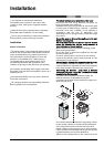
Preliminary information for installation of the hood:
Disconnect the hood during electrical connection, by
turning the home mains switch off.
Expansion wall plugs are provided to secure the hood
to most types of walls/ceilings. However, a qualified
technician must verify suitability of the materials in
accordance with the type of wall/ceiling. The
wall/ceiling must be strong enough to take the weight
of the hood.
Do not tile, grout or silicone this appliance to the wall.
Surface mounting only.
Do not fix chimney flue to furniture or fly over shelves
unless the chimney flue can be easily removed, in
case maintenance is ever required.
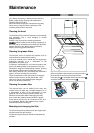
Where foreseen remove the grease collecting panels.
Remove the grease filter/s
Do not tile, grout or silicone this appliance to the wall.
Surface mounting only.
Do not fix chimney flue to furniture or fly over shelves
unless the chimney flue can be easily removed, in case
maintenance is ever required.
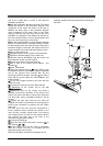
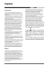
Assembling the chimney flue support/bracket (3 parts):
The three parts should be fixed with 4 screws, the
support extension is adjustable and should correspond
to the internal width of the telescopic chimney flue.
Assembling the deflector (only when a deflector
composed of 3 parts is supplied – the deflector should
be only for the filter version):
The three parts should be fixed with 2 screws, the
deflector extension is adjustable and should
correspond to the width of the chimney flue support, to
which it is then fixed.
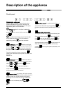
=
=
X
X
H
=
=
X
F
F
G
G
The minimum distance between the supporting surface
for the cooking vessels on the hob and the lowest part
of the range hood must be not less than 50cm from
electric cookers and 65 cm from gas or mixed cookers.
If the instructions for installation for the gas hob specify
a greater distance, this must be adhered to.
1.Draw a line corresponding to the centre line on the
Installation