


GB
7
PLEASE PHONE US TO REGISTER YOUR APPLIANCE AND ACTIVATE YOUR PARTS GUARANTEE ON 08448 24 24 24
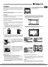
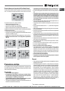
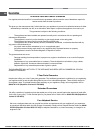
Replacing the nozzles on separate “double ame “ burners
1. Remove the grids and slide the burners from their housings. The burner
consists of 2 separate parts (see gure);
2. Unscrew the burers with a 7 mm wrench spanner. The internal burner
has a nozzle, the external burner has two (of the same size). Replace
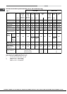
the nozzle with models suited to the new type of gas (see table 1).
3. Replace all the components by repeating the steps in reverse order.
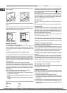
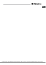
Replacing the Triple ring burner nozzles
1. Remove the pan supports and lift the burners out of their housing. The
burner consists of two separate parts (see pictures).
2. Unscrew the nozzles using a 7 mm socket spanner. Replace the nozzles
with models that are congured for use with the new type of gas (see Table
1). The two nozzles have the same hole diameter.
3. Replace all the components by completing the above operations in reverse
order.
• Adjusting the burners’ primary air
Does not require adjusting.
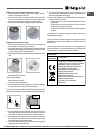
• Setting the burners to minimum
1. Turn the tap to the low ame position;
2. Remove the knob and adjust the adjustment screw, which is positioned
in or next to the tap pin, until the ame is small but steady.
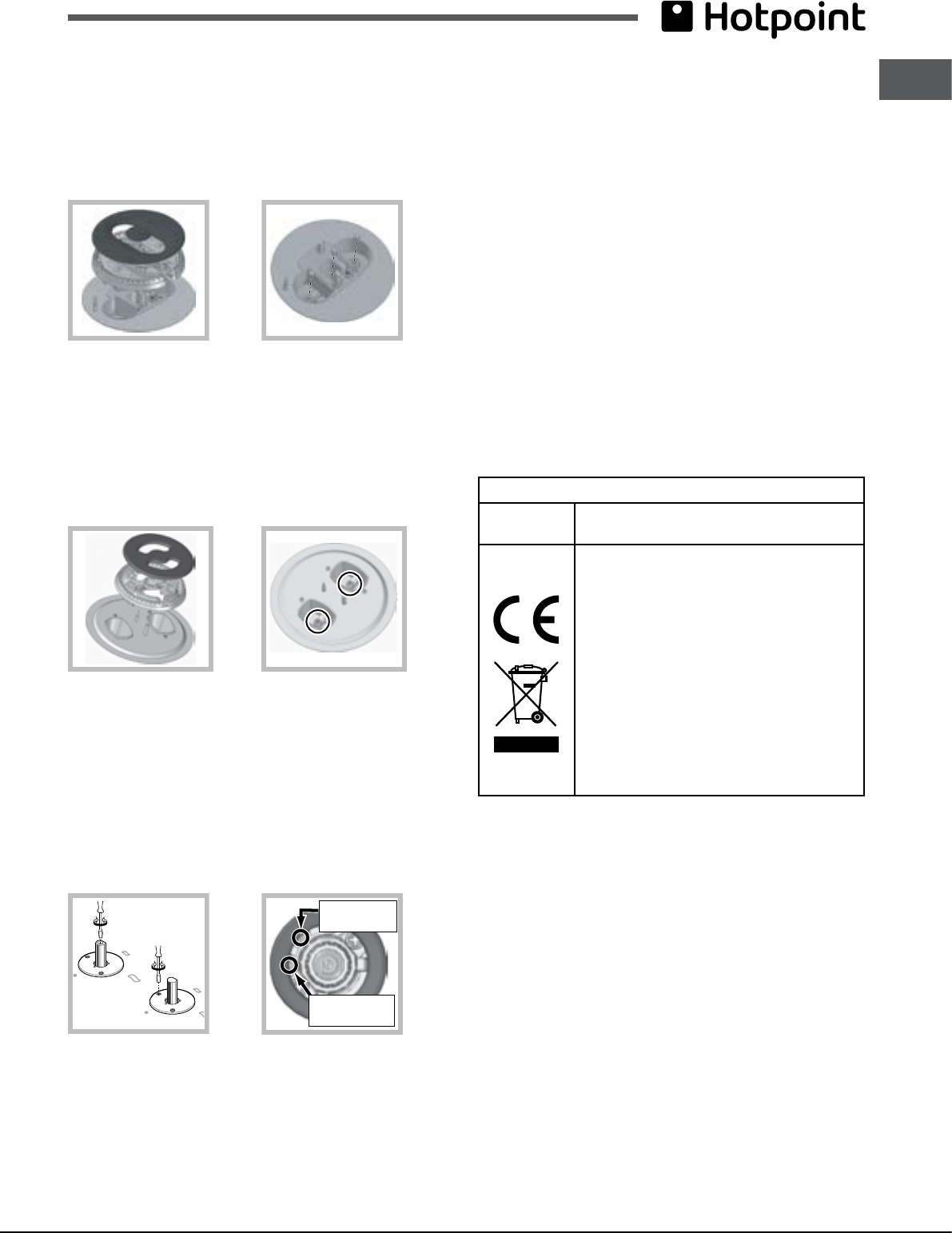
! In the event of single-control DRDA (DCDR) burners, adjustment can be
performed by intervening on the 2 screws located near the tap pin (see picture).
Inner DRDA (DCDR)
burner adjustment
Total DRDA
(DCDR) burner
adjustment
3. Having adjusted the ame to the required low setting, while the burner is
alight, quickly change the position of the knob from minimum to maximum
and vice versa several times, checking that the ame does not go out.
4. Some appliances have a safety device (thermocouple) tted. If the device
fails to work when the burners are set to the low ame setting, increase
this low ame setting using the adjusting screw.
5. Once the adjustment has been made, replace the seals on the by-passes
using sealing wax or a similar substance.
6. In the event of discrete-adjustment knobs with LED visualisation, turn the
knob to the minimum power setting them remove it and intervene on the
adjustment screw located near the tap pin.
7. Minimum setting adjustment of the DRDA (DCDR) burner with discrete
adjustment and LED visualisation:
• To adjust the outer ring, turn the knob anti-clockwise to the minimum
power position.
• To adjust the minimum power setting of the inner ring, turn the knob
clockwise to the minimum power position.
• Remove the knob and intervene on the adjustment screw located near
the tap pin.
! If the appliance is connected to liquid gas, the regulation screw must be
fastened as tightly as possible.
! Once this procedure is nished, replace the old rating sticker with one
indicating the new type of gas used. Stickers are available from any of our
Service Centres.
! Should the gas pressure used be different (or vary slightly) from the
recommended pressure, a suitable pressure regulator must be tted to the
inlet pipe (in order to comply with current national regulations).
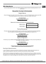
Electrical
connections
DATA PLATE
see data plate
This appliance conforms to the following
European Economic Community directives:
- 2006/95/EEC dated 12/12/06 (Low
Voltage) and subsequent amendments
- 2004/108/EEC dated 15/12/04
(Electromagnetic Compatibility) and
subsequent amendments
- 93/68/EEC dated 22/07/93 and
subsequent amendments.
- 2009/142/EEC dated 30/11/09 (Gas) and
subsequent amendments.
- 2012/19/EC and subsequent
amendments.