3
The minimum distance between the supporting surface
for the cooking vessels on the hob and the lowest part
of the range hood must be not less than 50cm from
electric cookers and 70cm from gas or mixed cookers.
If the instructions for installation for the gas hob specify
a greater distance, this must be adhered to.
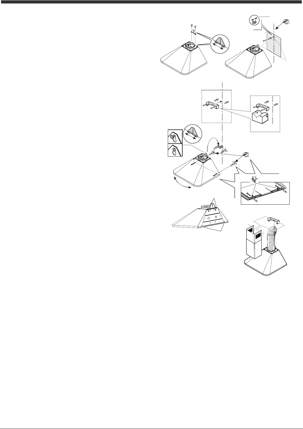
Fix the bracket behind the hood near the joining ring
(Fig. 4.1a).
Note: The bracket can be adjusted horizontally. This is
useful for successive small adjustments of the position
of the hood (Fig. 4.1b).
Draw a centerline on the wall from the cooking top to
the ceiling (Fig. 5.2).
Taking account of the distance from the cooking top,
mark the distance from the cooking top and position
the template (if supplied) to the wall on the mark (Fig.
5.3).
Mark the hole to be made, make it and insert the dowel
and partially screw 1 screw up (Fig. 5.4).
Fix the flue support to the wall as close as possible to
the ceiling (Fig. 6.1). In this phase, for the filter version,
also fix the baffle (Fig. 6.2).
Connect the hood to the partially screwed screw (Fig.
6.3a – if necessary the hood can be adjusted
horizontally, repositioning the bracket suitably – Fig-
6.3b)
Mark the 4 definitive fixing points of the hood:
2 below: removing the fat filters (Fig. 6.4), 2 above at
the sides of the bracket.
Remove the hood, make the holes, insert the dowels
(Fig. 6.5), replace the hood, insert and screw all the
screws up decisively (Fig.6.6 - Fig. 6.7).
Suction Version: the steam is sucked and sent outside
through a discharge tube that is fixed to the joining ring
positioned on the upper part of the hood.
Attention! If the hood is provided with a mounted
carbon filter, this must be removed.
The discharge air must not be discharged in a conduit
used for expelling fumes produced by gas or other fuel
apparatuses but must have an independent exit. All the
national regulations about the discharge of air must be
respected.
Filter Version: the filtered air passing through a carbon
filter is recycled into the surrounding environment.
Attention! If the hood is not provided with a carbon
filter it must be ordered and mounted before use.
Installing the telescopic flue.
Connect the hood to the power supply and fix the
telescopic flue to the support with two screws and let
the lower part slide until reaching the appropriate seat
on the upper side of the hood (Fig. 7).
2 x Ø 3,5x9,5
1a.
1b.
2.
3.
4.
÷ 5 mm
1 x Ø 8mm
1 x 5x45
Fig. 4 Fig. 5
1.
2 x Ø 8mm
2 x 5x45
2.
3a.
4.
5.
6.
3.
5.
5.
6.
6.
4.
7.
4.-5.-6.
4.-5.-6.
4 x Ø 8mm
4 x 5x45
3b.
2 x Ø 3,5x6,5
Fig. 6
Fig. 7
2 x Ø 3x9


