


8
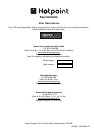
g) In the event the hob is not installed above a built-in
oven, a wood panel must be inserted as insulation. This
panel must be placed at least 20 mm from the bottom
of the cooktop itself.
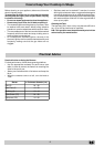
Important: When installing the hob above a built-in oven,
the oven should be placed on two wooden strips; in the
case of a joining cabinet surface, remember to leave a
space of at least 45 x 560 mm at the back.
560 mm.
45 mm.
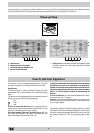
Gas connection for gas hob
The cooker should be connected to the gas-supply by a
corgi registered installer. During installation of this product
it is essential to fit an approved gas tap to isolate the
supply from the appliance for the convenience of any
subsequent removal or servicing. Connection of the
appliance to the gas mains or liquid gas must be carried
out according to the prescribed regulation in force, and
only after it is ascertained that it is adaptable to the type
of gas to be used. If not, follow the instructions indicated
in the paragraph headed “Adaptation to different gas types”.
In the case of connection to liquid gas, by tank, use
pressure regulators that conform to the regulation in force.
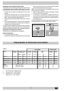
Important: For safety, for the correct regulation of gas
use and long life of the appliance, ensure that the gas
pressure conforms to the indications given in table 1
“Nozzle and burner characteristics”.
Connection to non-flexible tube
(copper or steel)
Connection to the gas source must be done in such a way
as to not create any stress points at any part of the
appliance.
The appliance is fitted with an adjustable, "L" shaped connector
and a gasket for the attachment to the gas supply. Should
this connector have to be turned, the gasket must be replaced
(supplied with the appliance).
The feeding connector of the gas to the appliance is a
threaded 1/2 gas male cylinder.
Connection to flexible steel tube
The gas feed connector to the appliance is a threaded,
male 1/2" connector for round gas pipe. Only use pipes
and sealing gaskets that conform to the standards currently
in force. The maximum length of the flexible pipes must
not exceed 2000 mm. Once the connection has been made,
ensure that the flexible metal tube does not touch any
moving parts and is not crushed.
Check the Seal
Once the appliance has been installed, make sure all the
connections are properly sealed, using a soapy water solution.
Never use a flame.
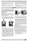
600mm min.
540mm min.
700mm min.
Fig. C
d) Should the hob be installed directly under a cupboard,
the letter should be at least 700mm (millimetres) from
the worktop, as shown in Fig. C.
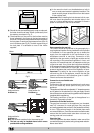
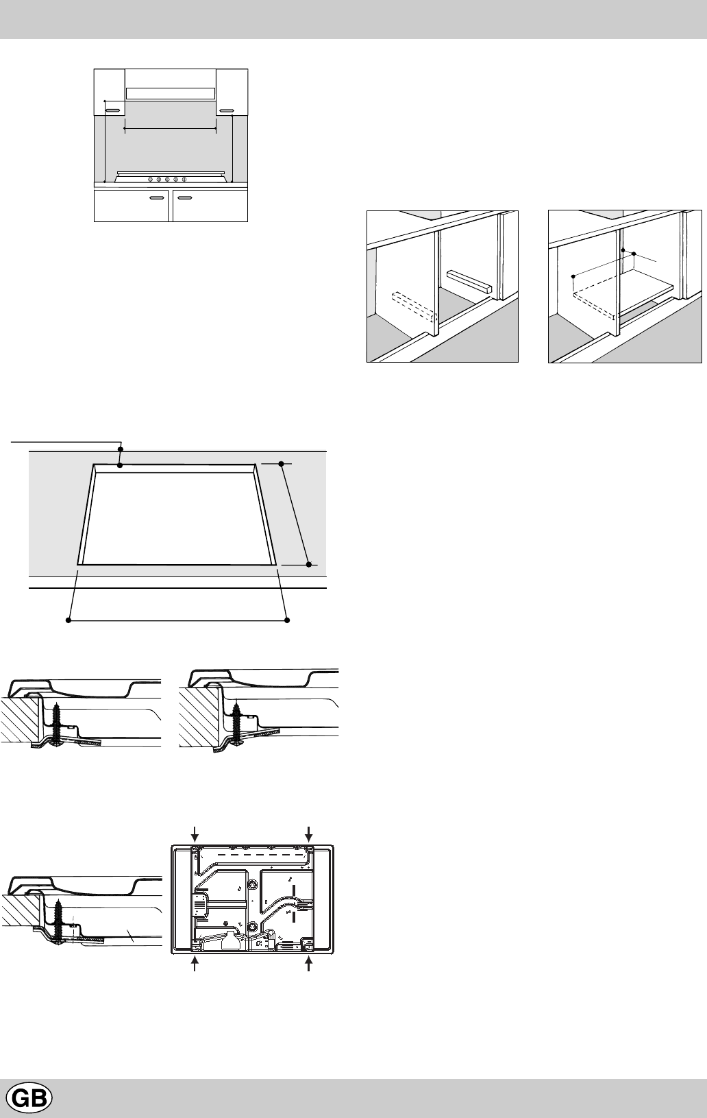
e) The dimensions of the room for the furniture must be
those indicated in the figures in the last two pages of
the cover. Fixing hooks are provided which allow to place
the hob plate on work tops that measure from 20 to 40
mm in thickness (see Fig. D). To obtain a good fixing of
the hob plate it is advisable to use all the hooks
supplied.
555
mm
475
mm
55
mm
Fig. D
Hook position for Hook position for
H=30mm top H=40mm top
Front
Hook position for Back
H=20mm top
N.B: Use the hook contained in the "accessories set"
f) The hob can only be installed above built-in ovens
provided with cooling ventilation.