14
The appliance must be installed only by a qualified per-
son in compliance with the instructions provided. The
manufacturer declines all responsibility for improper installa-
tion which may harm persons and animals and damage
property.
Important: The power supply to the appliance must be cut
off before any adjustments or maintenance work is done on
it.
Installation of Built-in Ovens
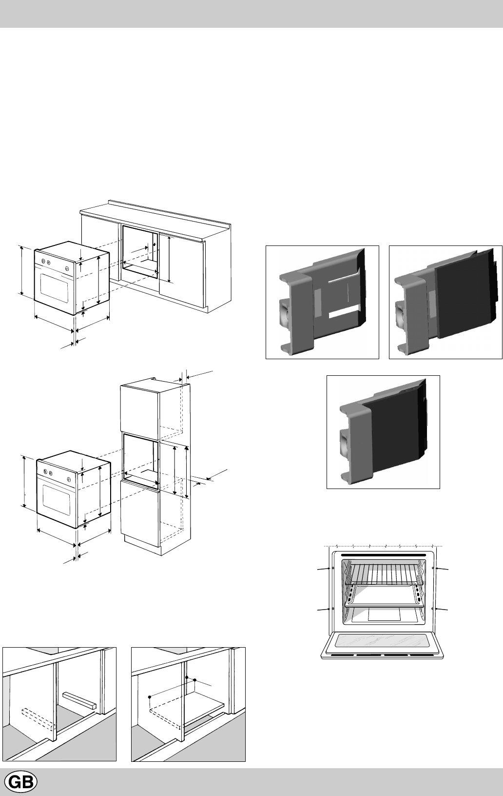
In order to ensure that the built-in appliance functions prop-
erly, the cabinet containing it must be appropriate. The figure
below gives the dimensions of the cut-out for installation un-
der the counter or in a wall cabinet unit.
In order to ensure adequate ventilation, the back panel of
the cabinet unit must be removed. Installing the oven so that
it rests on two strips of wood is preferable. If the oven rests
on a continuous, flat surface, there must be an aperture of
at least 45 x 560 mm.
The panels of the adjacent cabinets must be made of heat-
resistant material. In particular, cabinets with a veneer exte-
rior must be assembled with glues which can withstand
temperatures of up to 100 °C.
In compliance with current safety standards, contact with
the electrical parts of the oven must not be possible once it
has been installed.
All parts which ensure the safe operation of the appliance
must be removable only with the aid of a tool.
For the correct centring of your appliance, position the 4 tabs
on the sides of the oven in correspondence with the 4 holes
on the perimeter of the frame. In particular, if the cabinet side
panel:
• is 20 mm thick: the removable part of the tab must be
removed (Fig. A);
• is 18 mm thick: use the first groove, which is factory-set
(Fig. B);
• is 16 mm thick: use the second groove (Fig.C)
Fig. A Fig. B
Fig. C
To fasten the oven to the cabinet, open the door of the oven
and attach it by inserting the 4 wood screws into the 4 holes
located on the perimeter of the frame.
Electrical Connection
Those ovens equipped with a three-pole power supply cable
are designed to operate with an alternating current with the
voltage and frequency indicated on the data plate (located
on the appliance) and in the instruction manual. The wire for
earthing the appliance is yellow-green in colour.
595 mm.
595 mm.
24 mm.
545 mm.
5 mm.
567 mm.
23 mm.
593 mm.
45 mm.
558 mm.
N.B.: Installation in compliance with the consumption declaration
595 mm.
595 mm.
24 mm.
545 mm.
5 mm.
567 mm.
23 mm.
575-585 mm.
558 mm.
595 mm.
45 mm.
min.
45 mm.
min.
560 mm.
45 mm.
Installation


