


GB
23
PLEASE PHONE US TO REGISTER YOUR APPLIANCE AND ACTIVATE YOUR PARTS GUARANTEE ON 08448 24 24 24
Installation
Electrical Requirements
For your own safety, we recommend that your cooker
is installed by a competent person such as one who is
registered with NICEIC (National Inspection Council for
Electrical Installation Contracting). The cooker should
be installed in accordance with the latest edition of the
IEE Regulations.
Warning: This appliance must be earthed.
Electrical Connections
The installer must check that the voltage shown on
the rating plate corresponds with the house electricity
supply. The cooker must be supplied via a suitable
double pole isolating switch, having a contact
separation of at least 3mm in all poles placed in a
readily accessible position adjacent to the cooker. If
the cooker is to be wired into a connector unit, this
may be positioned behind the cooker providing the
following requirements are met:
i) The connector unit must not project from the wall
more than 25mm.
ii) The top of the connector must not be more than
130mm above floor level.
Remove the terminal cover at the rear base of the
cooker. Pass the cable through the cable clamp and
connect to the appropriate terminals provided.
Allow sufficient cable for any future servicing.
Tighten the screws on the cable clamp and replace the
cover. Make main connections in the connector unit or
cooker control unit. This appliance conforms to B.S. EN
55014 regarding suppression of Radio and Television
reception interference.
A double Pole control switch having a minimum rating
of 32 amps should be used to feed the cooker using
a suitably rated cable. Where a hob is fitted adjacent
to or over the cooker, a 45 amp Double Pole control
switch should be used to feed both units via separate
suitably rated cables.
We recommend a minimum of 4mm2 PVC insulated
twin and earth cable conforming to B.S. 6004 for
connection of each appliance.
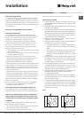
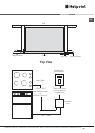
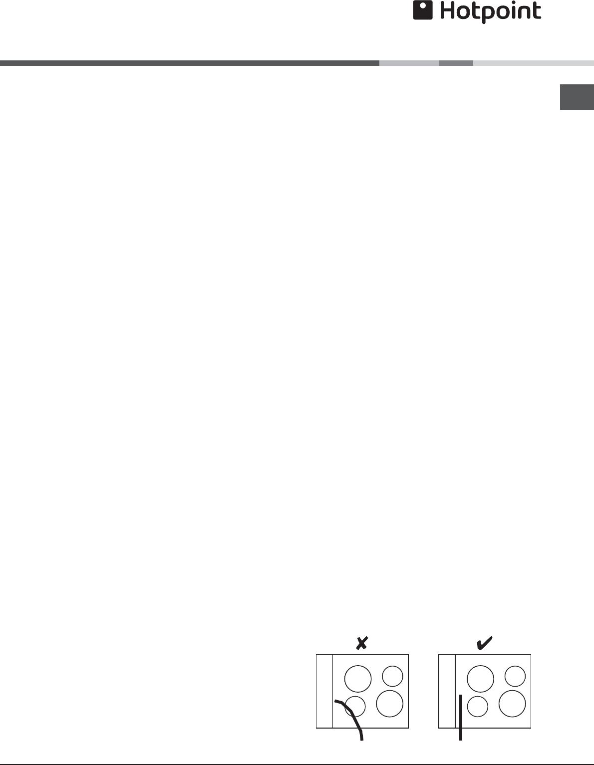
In all cases adhere to routing details (see fig. 5).
This appliance must not be installed over any other
appliance that generates heat such as a plinth heater.
Note: Due to many different types of installation, a
mains cable is not supplied with this product. The
installer will fit the correct type and length of cable.
GENERAL
The appliance is designed to be mounted on a floor
between two adjacent cabinets.
The cabinets must be securely fixed to the wall and the
cooker securely fixed to the cabinets.
This cooker must not be used free standing.
Note; This cooker must not be fitted on a platform.
FINAL INSTALLATION
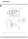
a. Ensure that the adjacent cabinets and the gap
between them have dimensions in accordance with
the diagram.
b. Assemble the plastic plugs provided into the fixing
brackets. See diagram.
c. Fix the fixing brackets to the sides of the adjacent
cabinets so that the centre line of the brackets are
570mm above the top of the plinth line and the front
face of the plastic plug is level with the front face
of the cabinet sides. See diagram.
d. Adjust the feet on the cooker to their minimum
position, i.e. fully screwed in.
e. Slide the cooker centrally into the space between
the cabinets ensuring the following:
i) The gap between the cabinet sides and the
cooker is even along the length of the cabinet
sides.
ii) The cable is routed away from any vents in the
rear panel and is not trapped between the co-
oker and the wall, adjacent cabinets or under
the feet
f. Adjust the feet using an open ended spanner until
the bottom of the cooker door is in line with the top
of the plinth. Using a spirit level, check that the
cooker is level in all directions.
g. Check that the plinth can be fitted. If necessary re
- adjust the feet and check that the cooker is level.
Then lock the feet into position by tightening the
lock nut using an open ended spanner.
h. Open the top oven door and fix the cooker to the
brackets through the holes in the side trims.
i. Fix the plinth in position.
j. Ensure that there is a minimum gap of 1mm betwe-
en the cooker side trim and the adjacent cabinet
doors or drawer fronts.
k. If a hob is to be installed directly above the cooker
it must not project downwards more than 20mm
below the underside of the work top. Any projection
of more than 10mm must not project more than
500mm from the wall.
Fig. 5