


IOD 150 Push Bar 150 (68) 115/60/1 Cord 3.0 15 139 (63)
Call factory for other dispensing options
ICE-O-Matic’s
®
machines are not designed for outdoor installations. ICE-O-Matic
®
remote condensers are designed for outdoor installations.
Machine requires voltage indicated on rating name plate. Failures caused by improper voltage are not considered factory defects. Extended
periods of operation at temperature exceeding limitations constitutes misuse under the terms of ICE-O-Matic
®
Manufacturer’s Limited Warranty,
resulting in a loss of warranty coverage. Specifications and design are subject to change without notice.
Model Dispenser Bin Storage Voltage Min. Circuit Maximum Shipping
No. Operated by: Applied Capacity Characteristics No. of Wires Ampacity Fuse Size Weight lbs. (Kgs.)
ORDERING AND SPECIFICATION INFORMATION
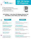
35
5/8
"
(890 mm)
22
1/4
"
(550 mm)
22"
(550 mm)
30
11/16
"
(767 mm)
OPERATING LIMITS
Ambient Temp. Range
Air & Water 50° - 100°F (10° - 38°C)
Water Temp. Range 40° - 100°F (4.5° - 38°C)
Water Pressures Min. 20 psi
Max. 120 psi
Electrical Voltage Min. -5% Max. +10%
IOD 150 Series ICE Dispenser
60 Hz
Air-Cooled lbs. (kgs.) 320 (145) 506 (230)
Water-Cooled lbs. (kgs.) 355 (161) 528 (240)
Remote-Cooled lbs. (kgs.) n/a n/a
Voltage Char. 115/60/1 115/60/1
1. Tested at 70º Air/50º Water.
2. All specifications and performace data are subject to normal manufacturing variances.
Options:
KWGFID water glass filler kit for IOD 22” 2 (1)
KBT15022 adapter for 22” cubers on 22” IOD 24(11)
Model
ICE 0320 ICE 0520
ICE PRODUCTION FOR OPTIONAL CUBE ICE MAKERS
— POUNDS (KILOGRAMS) PER 24 HOURS
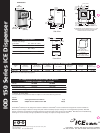
Dimensions
We reserve the right to make changes in design and construction at any time
without obligation.
2003 © ICE-O-Matic Rev Code: 4000A-08/03-SS
ICE-O-Matic 11100 E. 45th Avenue, Denver, CO 80239
Tel. 303 371-3737 Fax. 303 371-6296 www.iceomatic.com
®
I
S
O
9
0
0
1
C
E
R
T
I
F
I
E
D
FRONT
12 1/4
311 mm
22 1/4
565 mm
2 7/8
73 mm
Front View
RIGHT
2 3/4
70 mm
10 1/16
256 mm
CUP
CLEARANCE
7 3/4
197 mm
21 1/4
540 mm
29
737 mm
30 11/16
779 mm
35 5/8
905 mm
30 7/16
773 mm
Side View
TO FRONT TOP OF
DRIP TRAY
22
559 mm
7/16
11 mm (4) PLCS
18 5/8
473 mm
15
381 mm
3 1/2
89 mm
8 5/8
219 mm
18 7/16
468 mm
6 11/16
170 mm
TO FRONT OF
DRIP TRAY ON
COUNTER TOP
12
305 mm
9
229 mm
OPENING
MOUNTING
TEMPLATE
30 11/16
779 mm
29
737 mm
21 1/4
540 mm
RECOMMENDED COUNTER OPENING SIZE 9" X 12" FOR
UTILITIES AND TUBING. OPENING CAN BE LOCATED
ANYWHERE WITHIN THE SHADED AREA.
1 13/16
46 mm
1 5/16
33 mm
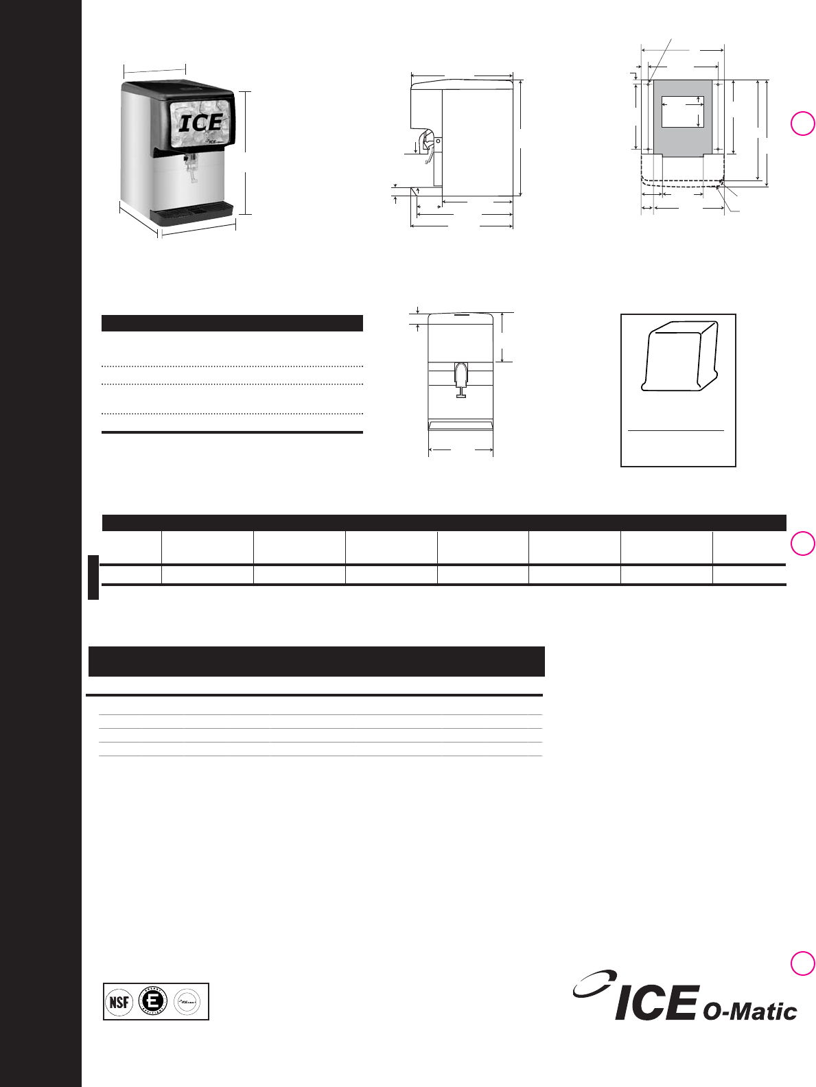
Half Cube
7/8" x 7/8" x 3/8"
(22mm x 22mm x 10mm)
Full Cube
7/8" x 7/8" x 7/8"
(22mm x 22mm x 22mm
)