


2569000242
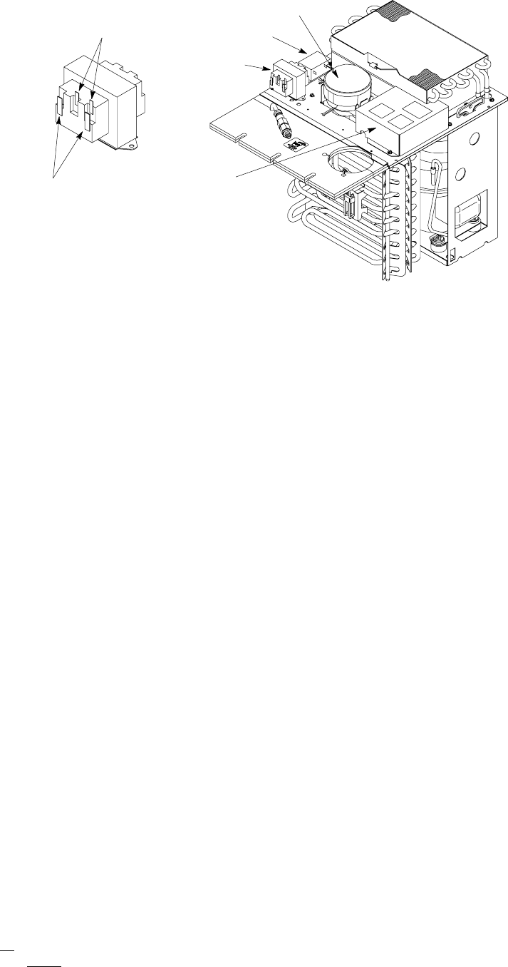
TRANSFORMER
AGITATOR MOTOR
ELECTRICAL
CONTROL BOX
PRIMARY
TERMINALS
(HIGH VOLTAGE)
SECONDARY
TERMINALS
(24 VAC)
VOLTAGE PROTECTOR
MODULE
FIGURE 1. TRANSFORMER/VOLTAGE PROTECTOR MODULE LOCATION
5. Place the transformer and the VOLTAGE PROTECTOR MODULE (item 1) on the refrigeration deck in
approximate locations as shown in Figure 1.
6. Using the transformer and the VOLTAGE PROTECTOR MODULE (item 1) as templates, mark their mount-
ing holes locations on the refrigeration deck.
7. Using a 9/64 drill bit, center punch and drill the four mounting holes in the refrigeration deck.
8. Install transformer and VOLTAGE PROTECTOR MODULE (item 1) on the refrigeration deck and secure
with SCREWS (item 5).
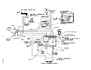
NOTE: Refer to Figure 2 (WIRING DIAGRAM) when making wiring connections between the Voltage
Protector Module and the Control Board.
9. Connect one end of the black ELECTRICAL WIRE (item 3) to “LIVE OUT” terminal on the Voltage Protec-
tor Module.
10. Disconnect Compressor black electrical wire from “SW. COMP” terminal on the Control Board.
11. Connect other end of the black electrical wire, connected to “LIVE OUT” terminal on the Voltage Protector
Module, to compressor black electrical wire disconnected from the control board “SW. COMP” terminal in
preceding step 10.
12. Connect one end of the blue ELECTRICAL WIRE (item 4) to “LIVE IN” terminal on the Voltage Protector
Module.
13. Connect other end of the blue ELECTRICAL WIRE (item 4) to “SW. COMP” terminal on control board
where compressor electrical wire was disconnected from in step 10 preceding.
14. Connect one end of the brown ELECTRICAL WIRE (item 2) to “L2” terminal on the control board. This con-
nection consist of two electrical wires connected to “L2” terminal with a piggy-back push on terminal.
15. Connect other end of the brown ELECTRICAL WIRE (item 2) to “NEUTRAL” terminal on the Voltage Pro-
tector Module.
16. Install control box cover and secure with two screws.
17. Connect electrical power to the Dispenser. Check Dispenser for proper operation. When refrigeration com-
pressor is operating, green light on the Voltage Protector Module will be illuminated. When refrigeration
compressor is not operating, the yellow light on the Voltage Protector Module will be illuminated.
18. Install hood on Dispenser and secure with screw.