General Information
Page A6
Installation Guidelines
Note: Installation should be performed by a Cornelius trained Service Technician.
For proper operation of the Cornelius ice machine, the following installation guidelines must be
followed. Failure to do so may result in loss of production capacity, premature part failures, and
may void all warranties.
Ambient Operating Temperatures
Minimum Operating Temperature: 50°F (10°C)
Maximum Operating Temperature 100°F (38°C), 110°F (43°C) on 50 Hz. Models.
Note: Cornelius products are not designed for outdoor installation.
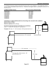
Incoming Water Supply (See Plumbing Diagram for line sizing Page A7-A12)
Minimum incoming water temperature: 40°F (4.5°C)
Maximum incoming water temperature: 100°F (38°C)
Minimum incoming water pressure: 20 psi (1.4 bar)
Maximum incoming water pressure: 60 psi (4.1 bar)
Note: If water pressure exceeds 60 psi (4.1 bar), a water pressure regulator must be
installed.
Drains: All drain lines must be installed per local codes. Flexible tubing is not recommended.
Route bin drain, purge drain and water condenser drain individually to a floor drain. The use of
condensate pumps for draining water is not recommended by Cornelius. Cornelius assumes no
responsibility for improperly installed equipment.
Water Filtration: A water filter system should be installed with the ice machine.
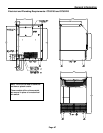
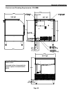
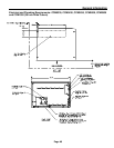
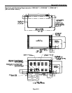
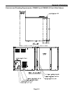
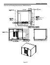
Clearance Requirements: Self contained air cooled ice machines must have a minimum of 6
inches (15cm) of clearance at the rear, top, and sides of the ice machine for proper air circulation.
Stacking: If the ice machines are to be stacked, refer to the instructions in the stacking kit.
Cornelius does not endorse stacking air-cooled ice machines.
Dispenser Application: A thermostatic bin control kit must be installed if the CCM series ice
machine is placed on a dispenser. A bin top may or may not be required. (Exception is the
CHD22/CHD30 Dispenser)
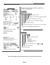
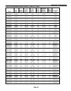
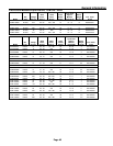
Electrical Specifications: Refer to the serial plate at the rear of the ice machine or the charts on
page A4 and A5.
Adjustments
Level the machine within 1/8 inch in all directions.
Check the bin control for proper adjustment, Page F9
Check the water in the water trough for proper level, Page D1
Check the ice bridge for proper thickness, Page F4
Check the cam switch adjustment. Page F8
Check the water regulating valve adjustment if water cooled, Page E2


