


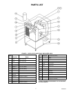

291256
INSTALLATION INSTRUCTIONS
LOCATION
Locate the chiller indoors in a well ventilated area with ambient temperatures in the range of 65° F to 100° F.
Allow a minimum of six inches of clearance around the chiller for proper air circulation. Avoid hot air discharge
from other equipment or enclosed areas where heat could build up and cause a rise in ambient temperature.
PLUMBING
Follow standard plumbing practices and local codes in making water connections. Piping that is exposed to high
ambient temperatures may need to be insulated to prevent condensation and/or significant liquid heat gain.
ELECTRICAL
All wiring must conform to the National Electric Code and any applicable local codes. The chiller must be:
1) Permanently wired by means of conduit from the junction box on the rear of the chiller cabinet to a properly
fused disconnect of proper amperage or:
2) Wired to a properly rated power cord and plugged into an outlet with appropriate disconnect and amperage
rating.
START–UP/OPERATION
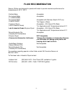
Before the Unit can be operated, it is important that the circulating system be filled with water (See Fluid Rec-
ommendations page). On systems with a reservoir, ensure that the drain plug is in place and the plug is secure.
Fill the reservoir through the fill port with clean water. The water level sight glass on the front panel will indicate
“Full” when enough water has been added. Once full, make the final connection to the inlet and outlet of the
chiller. On system without a reservoir, the pump should be primed before operation. Attach a water source to
the inlet of the chiller and fill the Unit with clean water. The system is filled when the water can be seen flowing
at the chiller outlet. Once full, make the final connection to the inlet of the chiller.
Turn the power switch to the “On” position. The switch will light indicating power to the Unit and the pump will
operate, the thermostat can be adjusted to the proper setpoint.
Set the standard digital thermostat to the desired setpoint as follows:
1) Push the “Set” button located to the right of the digital display. The current setpoint will show on the display.
2) While the current setpoint is displayed, push the “Up” or “Down” buttons until the desired setpoint shows on
the display.
3) Release all buttons. The display will show the system water temperature after a few seconds. The setpoint
can be viewed at any time by merely pushing the “Set” button.
If the Unit is provided with the electronic differential thermostat, the air probe will need to be located where am-
bient temperature is to be monitored. The setpoint will then be the temperature of the air probe. If this thermo-
stat is provided with a digital display, the setpoint can be checked by pushing the “Setpoint” button located on
the display. Releasing this button will display the system water temperature.
When the flow rate to the process is critical, a flow meter and valve should be installed in the line in order to ob-
tain the proper flow rate.