


2
92266
It is very important that the air intake and discharge sides of the chiller are not obstructed by other free standing
objects. A minimum of two feet of space on all four sides of the chiller will be sufficient to prevent air flow ob-
structions.
It is also important to direct any hot air discharge from other equipment away from the air intake side of the chill-
er. Condenser air entering the “CH” unit should be below 100_ F (38_ C) .Condenser air temperatures above
100_ F (38_ C) can cause the high pressure safety control to shut down the unit.
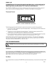
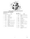
Electrical Connections
All wiring must conform to the National Electric Code and any applicable local codes.
The “CH” unit must be PERMANENTLY wired by means of electrical conduit to a properly fused disconnect of
proper amperage OR wired to a properly rated power cord and plugged into an outlet with the appropriate dis-
connect and amperage rating. The electrical junction box includes a four terminal strip for power supply connec-
tions. The DATA PLATE located beside the junction box indicates the phase, voltage and amperage of the
chiller.
Process Connections
Follow standard plumbing practices and local codes in making liquid connections. The Chiller inlet and outlet
connections are 3/4”--inch FPT couplings. It is recommended that 3/4--inch I.D. or larger flexible hose and tube
fittings be used as process connections. Lines should be routed with as few bends as possible. Prevent lines
from running near radiators, hot water pipes, etc. Any lengths of tubing that are exposed to high ambient tem-
peratures should be insulated to prevent condensation and/or significant liquid heat gain.
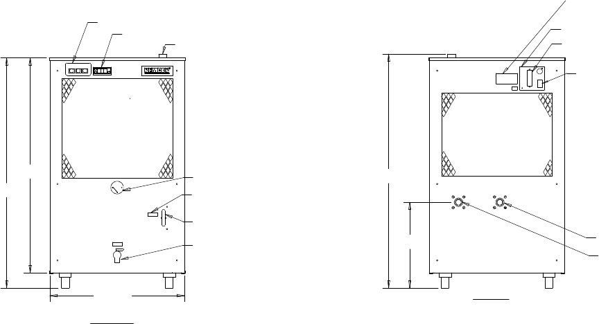
Once the system has been properly plumbed, it is important that the circulation system be filled with liquid. The
reservoir can be filled by removing the fill port cap located on top of the Chiller. After ensuring that the drain is
closed, fill the reservoir via the fill port with pure liquid until the liquid level sight glass on the front of the unit indi-
cates ”FULL”. The fill port cap should then be replaced prior to operation.
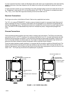
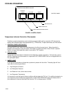
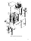
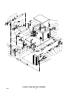
INTERLOCK STRIP
(IF APPLICABLE)
JUNCTION BOX
DATA PLATE/SERIAL NO.
OUTLET
TERMINAL STRIP
REAR
INLET
14.000
38.224
DRAIN
37.638
PRESSURE GAUGE
”FULL”
FRONT
35.138
21.963
RESERVOIR LEVEL INDICATOR
FILL PORT
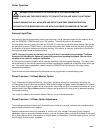
TEMPERATURE CONTROLLER
CONTROL PANEL
FIGURE 1. “CH” SERIES CHILLERS