


2
620914801
When servicing a REMCOR Chiller, it is important to note the information contained on the data plate located in
the upper rear of the Unit.
If technical assistance is needed, the phone technician will need the Serial Number of your Chiller. That informa-
tion is found on the Data Plate along with the model number, voltage requirement, and refrigerant information.
The serial Number is also needed when replacement parts are being ordered or for warranty claims. See
CHILLER WARRANTY PAGE.
Be sure to include the serial number on any documentation or billing information.
CHILLER INSTALLATION
Location of Chiller
THE CHILLER MUST BE LOCATED NEAR A PROPERLY GROUNDED ELECTRICAL OUTLET. THE CIR-
CUIT SHOULD BE FUSED AND NO OTHER ELECTRICAL APPLIANCE SHOULD BE CONNECTED TO THE
CIRCUIT. ALL ELECTRICAL WIRING MUST CONFORM TO NATIONAL AND LOCAL ELECTRICAL
CODES.
The Chiller must be located in a well ventilated, indoor area where ambient temperatures will remain above
40_ F (5_ C) and will never increase above 100_ F (38_ C). To obtain optimum cooling capacity, the ambient
temperature should be at or below 80_ F (27_ C).
It is very important that the air intake and discharge sides of the chiller are not obstructed by other free standing
objects. A minimum of two feet of space on all four sides of the chiller will be sufficient to prevent air flow ob-
structions.
It is also important to direct any hot air discharge from other equipment away from the air intake side of the chill-
er. Condenser air entering the “CH” unit should be below 100_ F (38_ C) .Condenser air temperatures above
100_ F (38_ C) can cause the high pressure safety control to shut down the unit.
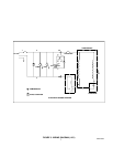
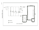
Electrical Connections
(see Figure 3)
All wiring must conform to the National Electric Code and any applicable local codes. The Chiller must be
permanently wired by means of electrical conduit to a properly fused disconnect of proper amperage or wired to
a properly rated power cord and plugged into an outlet with the appropriate disconnect and amperage rating.
The electrical junction box, located on the back panel of the Chiller, includes a four terminal strip for power
supply connection.
The data plate, located next to the junction box, includes the actual voltage, phase, and amperage of the Chiller.
START UP
WARNING: Never operate the Chiller with it’s panels removed.
Always use the power switch to turn off the Chiller when it is not being used.
Always ensure that all air inlets and outlets are free from obstruction.
Be sure that the reservoir is filled with fluid prior to powering up the unit (see Fluid
Recommendations page).
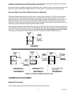
Process Water Flow, Units with Pump and Tank (Standard)
Follow standard plumbing practices and local codes in making water connections. The Chiller inlet and outlet
connections are 3/4”. Flexible hose and fittings are recommended for plumbing the system. A No. 20 mesh
strainer should be installed on the Chiller inlet to prevent foreign particles from entering the system and should
be cleaned monthly. Lines should be routed with as few bends as possible. Prevent lines from running near