


2620914101
F. Move black and red wires from left to right side of the beverage panel. Strip red/black wires and
reconnect to the keyswitch using wire connectors (item 4) provided.
G. Install beverage panel access covers.
4. Install Adaptor Kits if applicable for the type of ice makers used.
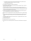
5. Apply self-adhesive gasket material (item 7) to the side of one Unit as indicated in Figure 1. Ends of the
gasket should fit tight to each other.
6. Place Units into position on the counter. The Units must be at the same height and sitting level. The
outside--outside dimension of the Units should be 60--3/8 inches (3/8--inch between the Units at the center).
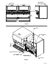
7. Remove one screw from each base at the rear of the Unit and install rear mounting plate (item 2) to main-
tain the proper spacing between the Units (see Figure 2).
8. Install front mounting plate (item 3) using the four beverage panel mounting screws at the center of the
Units. The rectangular plate is for use with the six or eight valve Units.
9. Apply RTV (item 5) at the gasket-cabinet joint to seal any gaps between the Units, on all sides of the gas-
ket.
10. Using one screw on each cabinet at the center of the Units (above the drip trays), install drip tray cover to
match color of the drip tray. The drip trays must be at the same height along the edges for cover to fit
properly.
11. Assemble two long #8--32 screws (item 9) to lower panel (item 1) using plastic washers (item 10). Install
lower panel assembly on Units.
12. Install Cornelius logo (item 11).
13. Replace hopper covers on the Units, manual fill Units.
14. Connect power cords for Ice/Beverage Dispenser to electrical outlet. Check Dispensers for proper opera-
tion.