


292181INS
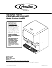
INSTALLATION INSTRUCTIONS
1. Locate the dispenser indoors on a level counter top.
A. LEG OPTION
Note: Before installing legs, the plastic plugs must be removed.
Unpack the four (4) legs and install them into the threaded holes provided in the bottom of the unit. The
installer must provide flexibility in the product and utility supply lines to permit shifting the position of the
dispenser sufficiently to clean the area beneath it.
Rotate the line support bracket, located under base, to the down position and route all the lines above
the bracket.
B. COUNTER MOUNTING
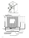
The ice dispenser must be sealed to the counter. The MOUNTING TEMPLATE (see Figure 3)
indicates where openings can be cut in the counter. Locate the desired position for the dispenser, then
mark the outline dimensions on the counter using the MOUNTING TEMPLATE. Cut openings in the
counter.
Rotate the line support bracket, located under base, to the up position and route all the lines below the
bracket.
Apply a continuous bead of National Sanitation Foundation (NSF) listed silastic sealant (Dow 732 or
equal) approximately 1/4” inside of the unit outline dimensions and around all openings. Then, position
the unit on the counter within the outline dimensions. All excess sealant must be wiped away
immediately.
2. The beverage tubes, drain tube and power cord are routed through the large opening in the bottom of the
unit. See the MOUNTING TEMPLATE (see Figure 3), for locating the required clearance hole in the counter
for these utility lines.
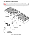
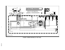
3. DRIP TRAY DRAIN ASSEMBLY (see Figure 1). Route the drain tube to an open drain with the end of the
tube above the “flood” level of the drain. Use the tubing, fittings, clamps, and insulation provided with the Dis-
penser to assemble the drain. The completed drain line must pitch continuously downward and contain no
“traps” or improper drainage will result.
NOTE: This equipment must be installed with adequate backflow protection to comply with federal, state,
and local codes.
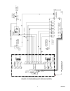
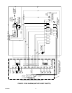
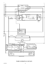
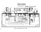
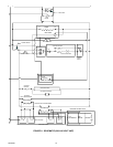
4. Connect the beverage system product tubes as indicated in the applicable Flow Diagram. This work should
be done by a qualified Service Person. Any non-carbonated water tubing must be connected to the outlet of
the check valve.
Note: See applicable Flow Diagram (see Figure 4 through 7) or decal on lower front panel of the unit for
the location of syrup and water connections.
Note: Water pipe connections and fixtures directly connected to a potable water supply shall be sized,
installed and maintained according to Federal, State and Local Laws.
5. Clean the hopper interior (see Owner’s Manual P/N 92108 for cleaning instructions).
6. Connect the power cord to a 120 volt, 60 cycle, 3–wire grounded receptacle. For 220–240 volt units, a
3–wire power cord is provided. An adapter plug for the particular country will need to be provided by the
equipment Installer.