


78
166240004
12/1/94
Rev 3/4/96
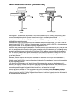
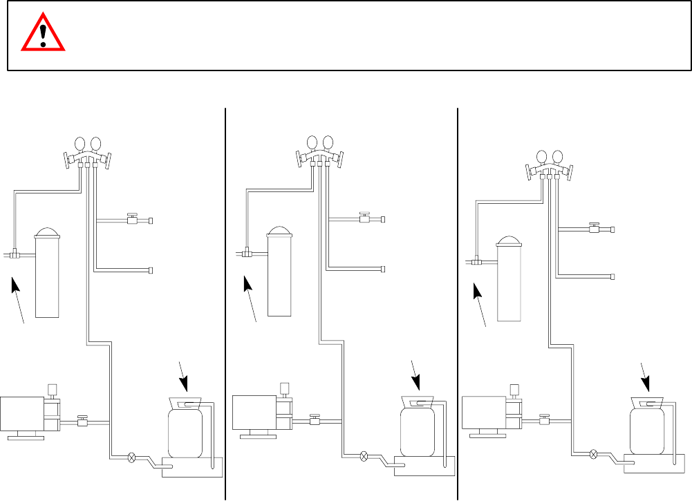
REMOTE SYSTEM EVACUATION/RE-CHARGE
All field repairs to the sealed system must start with a total discharge of the system following the requirements
of the Clean Air Act of July, 1992.
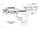
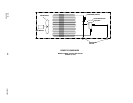
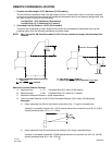
Proper evacuation of the total remote system will require a three (3) point hook-up of your manifold and hose
set, (see drawing):
Point #1 - Cuber receiver outlet valve
Point #2 - Cuber high side service valve
Point #3 - Cuber low side service valve
Evacuation:
1. With cuber power supply turned “OFF” disconnect and insulate all 3 compressor leads at the compressor.
Turn power supply on, place power switch in the “on” position. This will energize (open) the Liquid Line so-
lenoid allowing evacuation of the Liquid Line between the solenoid and the expansion valve(s).
2. Evacuate system to 200/250 microns or less. At this point, there should be a holding test of five(5) minutes.
You may expect a slight loss of vacuum as normal. A rapid rise to normal atmospheric pressure indicates
moisture still present in the system. On a “wet” system, it will prove beneficial to use heat lamps to warm
the compressor dome and evaporator surface during evacuation.
3. Turn cuber power switch OFF. Reconnect compressor leads.
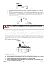
4. *After proper evacuation hold test has been performed, the refrigerant charge should be “dumped” into the
receiver until the pressure equalizes, stopping the flow. Do not try to throttle the refrigerant flow. Doing so
will allow system pressure to balance too soon. The high-side service valve should be closed and the bal-
ance of the charge fed slowly through the suction side service valve with the compressor operational. Con-
trol the feed rate at no faster than four (4) ounces [113.g] per minute to ensure the compressor oil does not
become too saturated with refrigerant resulting in a loss of compressor lubrication.
5. All refrigerant re-charging must be weighed into the system, utilizing an electronic charging scale. DO NOT
attempt to recharge the system by sight glass, system pressure, amperage, frost line or sweat patterns.
6. Always leak check entire system after recharge.
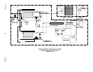
CAUTION: Before programming the electronic scales to “dump” the charge, de-energize
the liquid line solenoid, close the shut-off valve on vacuum pump and low side of the
manifold set.
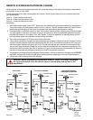
EVACUATION
MANIFOLD SET
OPEN
RECEIVER
OPEN
RECEIVER
OUTLET
VA LV E
OPEN
VACUUM
PUMP
ELECTRONIC
SCALE
CHARGING
CYLINDER
CLOSED
CLOSED
LOW
SIDE
SERVICE
VA LV E
HIGH SIDE
SERVICE
VA LV E
OPEN
OPEN
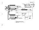
1ST STAGE CHARGING
MANIFOLD SET
OPEN
RECEIVER
OPEN
RECEIVER
OUTLET
VA LV E
OPEN
VACUUM
PUMP
ELECTRONIC
SCALE
CHARGING
CYLINDER
CLOSED
LOW
SIDE
SERVICE
VA LV E
HIGH SIDE
SERVICE
VA LV E
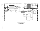
2ND STAGE CHARGING
COMPRESSOR OPERATING
MANIFOLD SET
RECEIVER
RECEIVER
OUTLET
VA LV E
OPEN
VACUUM
PUMP
ELECTRONIC
SCALE
CHARGING
CYLINDER
CLOSED
CLOSED
LOW
SIDE
SERVICE
VA LV E
HIGH SIDE
SERVICE
VA LV E
OPEN
OPEN
CLOSED
CLOSED
OPEN
CLOSED
CLOSED