5
GB
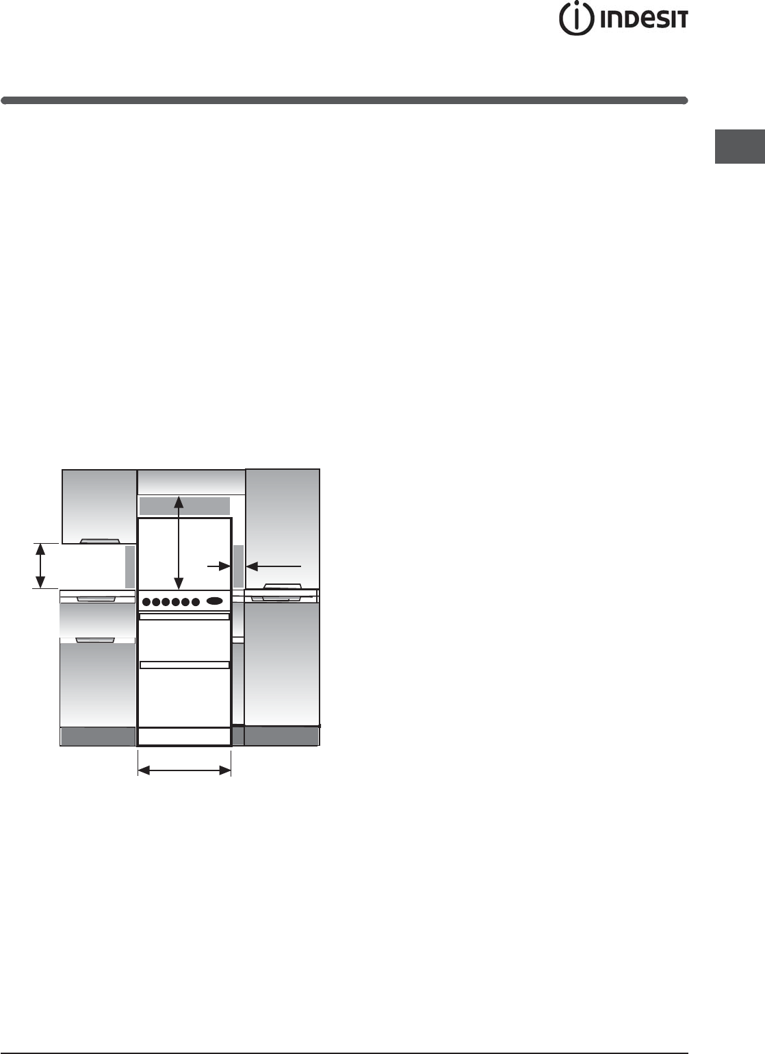
Installation
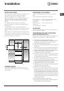
SPACE FOR FIXING
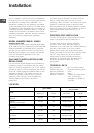
The cooker can be close fitted below hotplate level.
This requires a minimum distance of 600mm
between cupboard units of hotplate height.
When installing next to a tall cupboard, partition or
wall, for a minimum distance of 400mm above
hotplate level, allow a side clearance of at least
65mm.
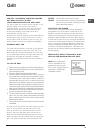
The diagram below illustrates the minimum
clearance between the cooker and adjacent walls,
cupboards etc.
The wall behind the cooker, 50mm below and
450mm above, and the width of the cooker, must be
a non-combustible material such as ceramic wall
tiles.
If the cooker is to be fitted close to a corner on the
left hand side, ensure that there is a clearance of at
least 50mm to allow the main oven door to open fully
for when removing oven shelves.
65 mm Min
840 mm Min
400 mm Min
600 mm Min
750mm Min
COOKER HOODS
If a cooker hood is to be installed, refer to the
cooker hood manufacturers' instructions regarding
fixing height.
UNPACKING THE COOKER
Unpack the components from inside the grill and
oven.
Check that the following parts are present:
Grill pan and grid Top oven/grill shelf heat shield
Pan supports Main oven shelves (2)
Enamelled
burner caps (4) Top oven/grill shelf (1)
Aluminium
burner bodies(4) Literature
LEVELLING
Four skid feet are fitted which can be adjusted up or
down to level the cooker.
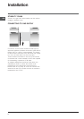
CONVERSION FOR USE ON BUTANE
(G30) OR PROPANE (G31)
Each burner requires the injector to be replaced and
bypass screws adjusted or replaced as follows:
1. Remove the loose hotplate burner parts.
2. Using a 7mm socket, replace the hotplate injectors
as appropriate (see table on previous page).
3. Re-position the loose burner parts.
4. Remove the enamelled baffle at the front of the grill
(2 screws).
5. Remove the screw on the right hand side of the
burner and gently slide the burner off the injector.
6. Using a 7mm socket, replace the grill injector as
appropriate (see table on previous page).
7. Re-assemble the burner and baffle.
8. Inside the top oven, remove the central screw
securing the burner retainer. Slide the retainer to
the right slightly and lift away.
9. Lift the burner assembly and place on the floor of
the oven to the right of the burner opening.
10.Using a 7mm socket, replace the oven injector as
appropriate (see table on previous page).
11.Re-assemble the oven burner and retainer.
12.Replace the main oven injector following the same
procedure as for the top oven.
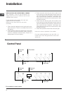
13.Carefully pull off the control knobs.
14.Using a narrow flat bladed screwdriver rotate the
bypass screws fully clockwise. The main oven
thermostat bypass screw is located on the body of
the thermostat below the spindle, the top oven
thermostat bypass screw is located on the body of
the thermostat to the right of the spindle and the
hotplate tap bypass screws are located down the
centre of the spindle.
15.Re-assemble the control panel parts.
16.Secure the self-adhesive LPG conversion label over
the gas details on the data badge.