5
24V Water Solenoid
1 GPM Flow Control
24V Water Solenoid
7 GPM Flow Control
2 3 4 6 7 7 13
Disposer
14 M1/M3 M4/M6M2 M5 M7 NC NC
1 3 2
L1 L2
L1 L2
On
Off
Neutral
Hot
Pre-wired in
panel to
contactors
Power Supply
Motor Leads
Panel Ground Lug
Control Center Connection
To Power Supply
4 6 5 7
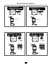
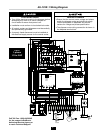
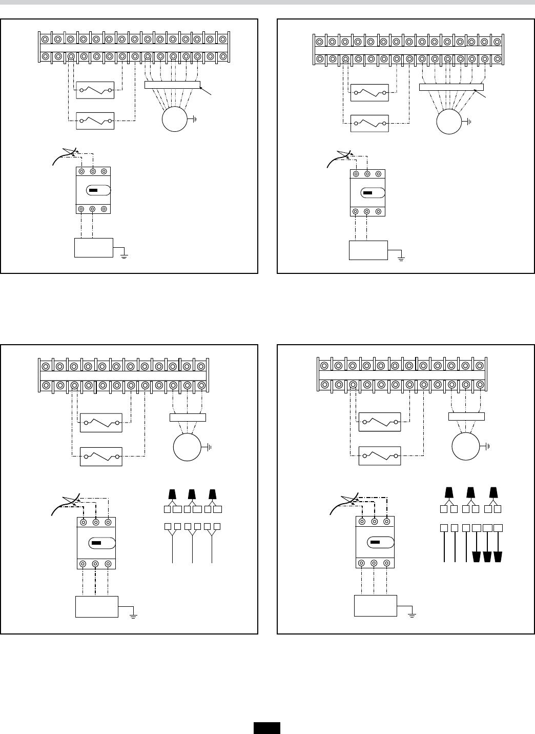
Figure 3. Incoming 120 V Single Phase Line Power
24V Water Solenoid
1 GPM Flow Control
24V Water Solenoid
7 GPM Flow Control
2 3 4 6 7 7 13
Disposer
14 M1 M3/M4M2 M5 M6 M7 NC
1 2 3
L1 L2
L1 L2
On
Off
Neutral
Hot
Pre-wired in
panel to
contactors
Power Supply
Motor Leads
Panel Ground Lug
Control Center Connection
To Power Supply
4 5 6 7
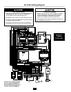
Figure 4. Incoming 208-240 V Single Phase Line Power
24V Water Solenoid
1 GPM Flow Control
24V Water Solenoid
7 GPM Flow Control
L1 L2 L3
L1 L2 L3
On
Off
Hot
Pre-wired in
panel to
contactors
Power Supply Panel Ground Lug
2 3 4 6 7 7 13
14 NC M1 M2 M3
Disposer
M1 M2 M3
1
4 7 5 6 9
MOTOR LEAD WIRE#
M1 M2 M3
8
2 3 10 11 12
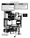
Figure 6. Incoming 380-460 V Three Phase Power
24V Water Solenoid
1 GPM Flow Control
24V Water Solenoid
7 GPM Flow Control
L1 L2 L3
L1 L2 L3
On
Off
Hot
Pre-wired in
panel to
contactors
Power Supply Panel Ground Lug
2 3 4 6 7 7 13
14 NC M1 M2 M3
Disposer
M1 M2 M3
M1
M2 M3
1
4 10 5 6 12
MOTOR LEAD WIRE#
11
7 2 8 3 9
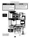
Figure 5. Incoming 208-230 V Three Phase Line Power
Electrical Connection Diagrams


