With all of the components secured in place,
the tubing connections can be made. When
routing the tubing between components,
several guidelines should be observed:
•Tubing runs should generally follow the
contour of the cabinet rather than interfere
with the cabinet storage area.
•Arrange the tubing so that there are no
sharp bends.Leave some extra length in the tubing for ease of servicing,
then cut tubing to the desired length.
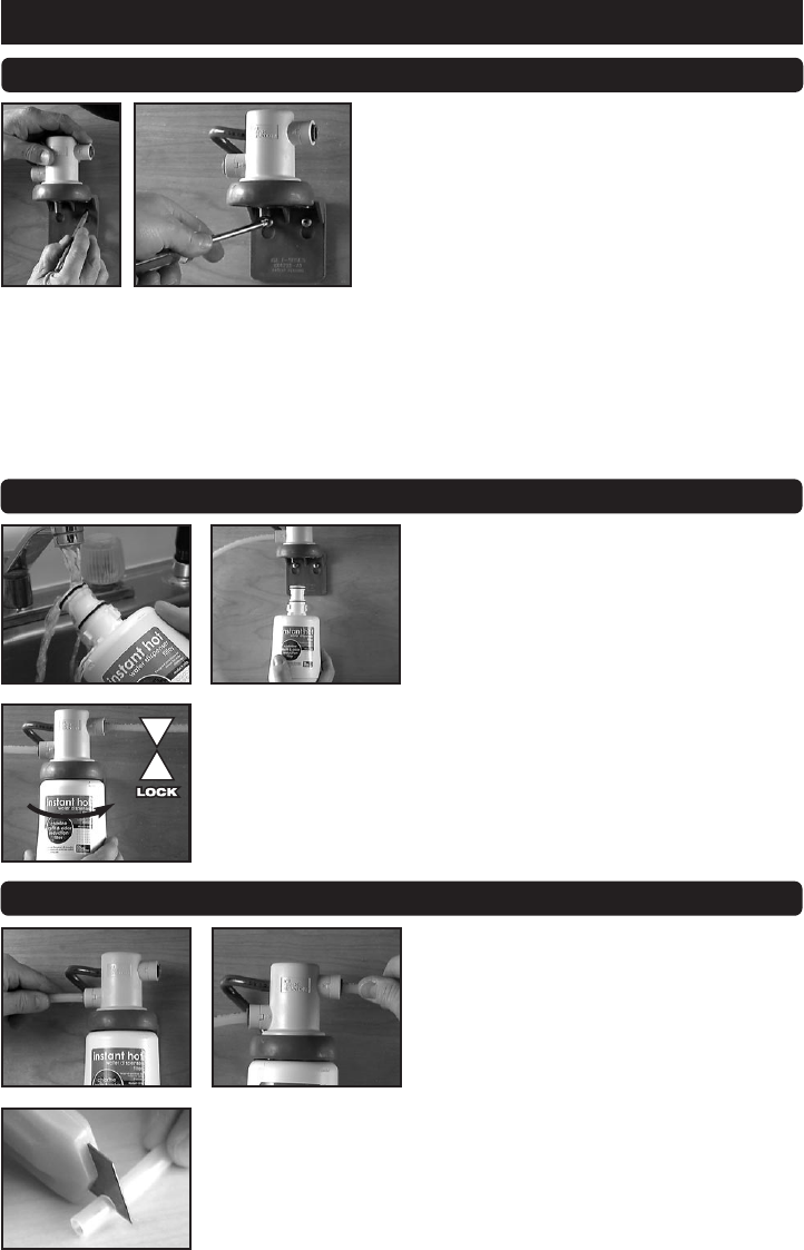
• Insert tubes completely into all quick-connect fittings to the stop
(minimum depth of 1/2").Completely insert 3/8" polyethylene tubing
into inlet and outlet sides of the filter head.
•The polyethylene tubes can be cut,but caution should be exercised to
ensure that a clean (burr-free) cut is made,perpendicular to the tube.
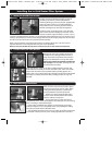
1. Mount the Head & Filter Bracket
Install the head and bracket assembly so that all
plumbing connections can be made without
stretching,kinking,or pinching the 3/8" polyethylene
tubes.The tubes can be cut to make installation
easier.Make sure the mounting location allows for
the filter cartridge to be removed and replaced.
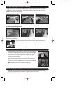
The filter system is equipped with a vent line that
opens when the filter cartridge is removed. Under
normal conditions,approximately 2 ounces (~60 cc)
of water is discharged from the vent. To conveniently redirect this discharge,a 6”section of gray
tubing is provided.If you wish to install,simply slide one end of the gray tube over the vent and
the other end into the hole on the head & bracket assembly.
With a pencil,mark the mounting hole locations.Pre-drilling pilot holes (1/8
"
dia.) may be
required.
Attach the mounting bracket using the screws provided.
Note:Do not locate the filter directly above an electrical outlet or other electrical components.
Installing the In-Sink-Erator Filter System
2. Connect Filter into Filter Bracket
Remove the cap from cartridge.Inspect the
cartridge for any damage.Make sure the O-
rings are present and positioned correctly in
the grooves.Moisten the O-rings with water.
Do not use petroleum products to lubricate
the O-rings. Insert the filter cartridge into the
head & bracket assembly.
Align the “IN/OUT”mark on the filter cartridge with the mark on the
head & bracket assembly and rotate until the “LOCK”mark on the filter
aligns with the mark on the head & bracket assembly (approx.90˚).
Note:If the O-ring is breached,water will leak from the head and bracket
assembly.To remedy, remove the filter cartridge,inspect O-ring and
reinstall.
3. Make Plumbing Connections
43386 Filter Owner's Manual.qxd 9/26/02 11:58 AM Page 3 Greg Leber Jobs:39237 ISE HWD Owner's Manual:43386 HWD Filter


