


FOR SERVICE PERSONNEL: Jackson MSC Inc. provides technical support for all of the dishmachines detailed in this manu-
al. We strongly recommend that you refer to this manual before making a call to our technical support staff. Please have this
manual with you when you call so that our staff can refer you, if necessary, to the proper page. Technical support is available
from 8:00 a.m. to 5:00 p.m. (EST), Monday through Friday. Technical support is not available on holidays. Contact technical
support toll-free at 1-888-800-5672. Please remember that technical support is available for service personnel only. Non-ser-
vice personnel should refer to the list of provided service agencies in this manual for local service support.
VISUAL INSPECTION: Before installing the unit, check the container and machine for damage. A damaged container is an indi-
cator that there may be some damage to the machine. If there is damage to both the container and machine, do not throw away
the container. The dishmachine has been inspected and packed at the factory and is expected to arrive to you in new, undam-
aged condition. However, rough handling by carriers or others may result in there being damage to the unit while in transit. If
such a situation occurs, do not return the unit to Jackson; instead, contact the carrier and ask them to send a representative to
the site to inspect the damage to the unit and to complete an inspection report. You must contact the carrier within 48 hours of
receiving the machine. Also, contact the dealer through which you purchased the unit.
UNPACKING THE DISHMACHINE: Once the machine has been removed from the container, ensure that there are no miss-
ing parts from the machine. This may not be obvious at first. If it is discovered that an item is missing, contact Jackson imme-
diately to have the missing item shipped to you.
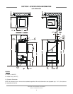
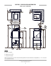
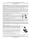
LEVEL THE DISHMACHINE: The dishmachine is designed to operate while being level. This is
important to prevent any damage to the machine during operation and to ensure the best results
when washing ware. The unit comes with adjustable bullet feet, which can be turned using a pair
of channel locks or by hand if the unit can be raised safely. Ensure that the unit is level from side
to side and from front to back before making any connections.
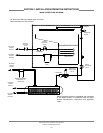
PLUMBING THE DISHMACHINE: All plumbing connections must comply with all applicable local,
state, and national plumbing codes. The plumber is responsible for ensuring that the incoming water line is thoroughly flushed
prior to connecting it to any component of the dishmachine. It is necessary to remove all foreign debris from the water line that
may potentially get trapped in the valves or cause an obstruction. Any valves that are fouled as a result of foreign matter left in
the water line, and any expenses resulting from this fouling, are not the responsibility of the manufacturer.
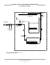
CONNECTING THE DRAIN LINE: The drain for the models covered in this manual are gravity discharge drains. All piping from
the 1 1/2” FNPT connection on the waste accumulator must be pitched (1/4” per foot) to the floor or sink drain. All piping from
the machine to the drain must be a minimum 1 1/2” NPT and shall not be reduced. There must also be an air gap between the
machine drain line and the floor sink or drain. If a grease trap is required by code, it should have a flow capacity of 5 gallons
per minute.
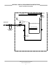
WATER SUPPLY CONNECTION: Ensure that you have read the section entitled
“PLUMBING THE DISHMACHINE” above before proceeding. Install the water supply
line (3/4” pipe size minimum) to the dishmachine line strainer using copper pipe. It is
recommended that a water shut-off valve be installed in the water line between the main
supply and the machine to allow access for service. The water supply line is to be capa-
ble of 20A5 PSI “flow” pressure at the recommended temperature indicated on the data
plate.
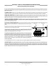
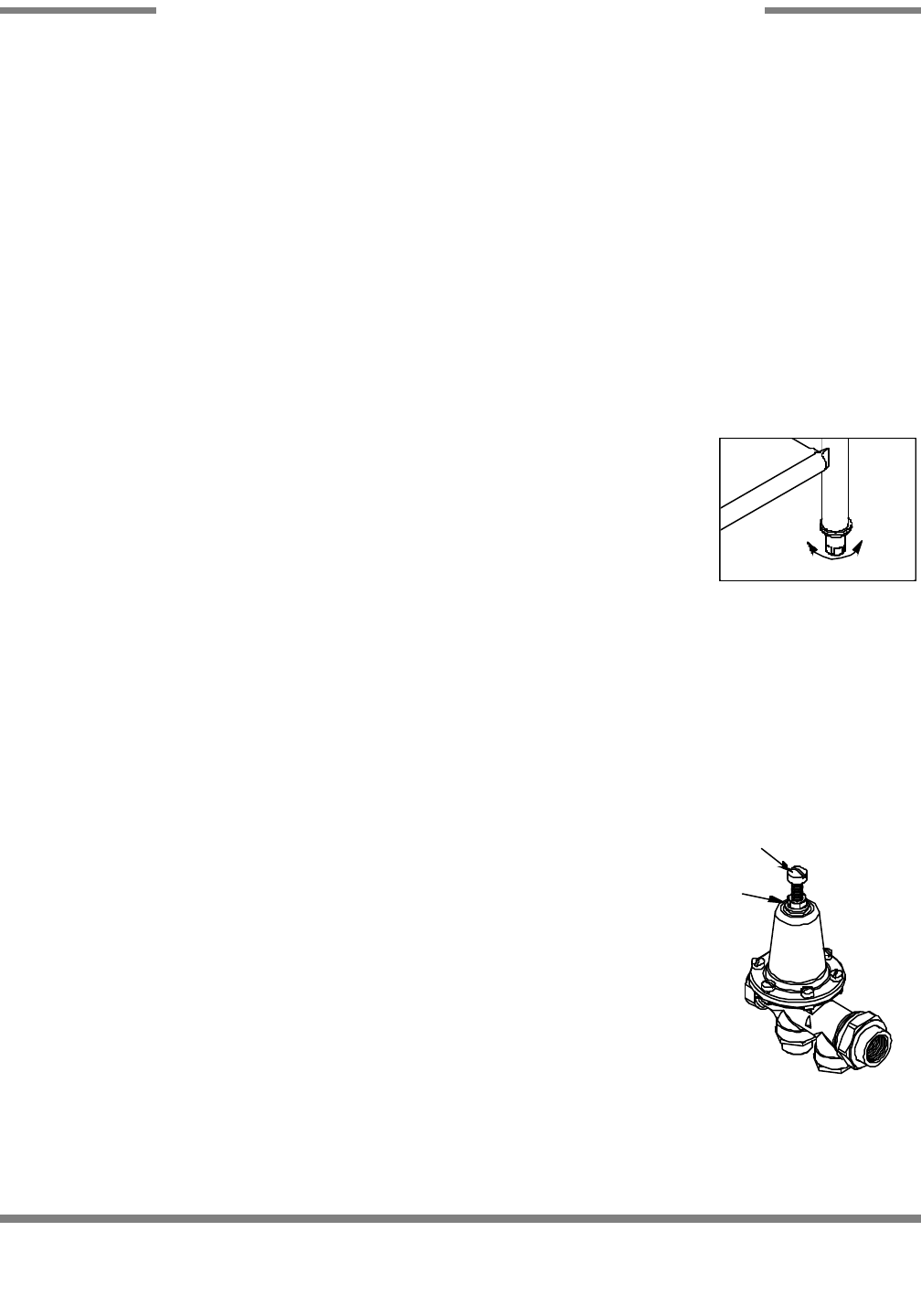
If the water level is too low or too high, check the incoming water pressure. It should be
20 A 5 PSI. Too high of pressure results in too much water; too low of pressure results
in too little water. To adust the regulator, loosen the nut at the top, this will allow you to
screw or unscrew the adjustment. With a screwdriver, turn the adjuster clockwise to
increase pressure or counter clockwise to decrease it.
In areas where the water pressure fluctuates or is greater than the recommended pres-
sure, it is recommended that a water pressure regulator be installed.
Do not confuse static pressure with flow pressure. Static pressure is the line pressure in a “no flow” condition (all valves and
services are closed). Flow pressure is the pressure in the fill line when the fill valve is opened during the cycle.
300X Series Technical Manual 7610-002-64-22
Issued: 07-26-2006 Revised: N/A
SECTION 2: INSTALLATION/OPERATION INSTRUCTIONS
INSTALLATION INSTRUCTIONS
8
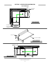
Frame with Adjustable Foot
Raise
Lower
Incoming Plumbing Connection
Adjusting screw
Locking nut