


VISUAL INSPECTION: Before installing the unit, check the con-
tainer and machine for damage. A damaged container is an indi-
cator that there may be some damage to the machine. If there is
damage to both the container and machine, do not throw away the
container. The dishmachine has been inspected and packed at
the factory and is expected to arrive to you in new, undamaged
condition. However, rough handling by carriers or others may
result in there being damage to the unit while in transit. If such a
situation occurs, do not return the unit to Jackson; instead, contact
the carrier and ask them to send a representative to the site to
inspect the damage to the unit and to complete an inspection
report. You must contact the carrier within 48 hours of receiving
the machine. Also, contact the dealer through which you pur-
chased the unit.
UNPACKING THE DISHMACHINE: Once the machine has been
removed from the container, ensure that there are no missing
parts from the machine. This may not be obvious at first. If it is dis-
covered that an item is missing, contact Jackson immediately to
have the missing item shipped to you.
LEVEL THE DISHMACHINE: The dishmachine is designed to
operate while being level. This is important to prevent any dam-
age to the machine during operation and to ensure the best
results when washing ware. The unit comes with adjustable bullet
feet, which can be turned using a pair of channel locks or by hand
if the unit can be raised safely. Ensure that the unit is level from
side to side and from front to back before making any connec-
tions.
PLUMBING THE DISHMACHINE: All plumbing connections must
comply with all applicable local, state, and national plumbing
codes. The plumber is responsible for ensuring that the incoming
water line is thoroughly flushed prior to connecting it to any com-
ponent of the dishmachine. It is necessary to remove all foreign
debris from the water line that may potentially get trapped in the
valves or cause an obstruction. Any valves that are fouled as a
result of foreign matter left in the water line, and any expenses
resulting from this fouling, are not the responsibility of the manu-
facturer.
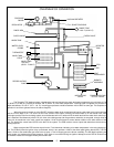
CONNECTING THE DRAIN LINE: The drain for the Tempstar-
TGP is a gravity discharge drain. All piping from the 1 1/2 ” FNPT
connection on the waste accumulator must be pitched (1/4” per
foot) (2.083 cm per meter) to the floor or sink drain. All piping from
the machine to the drain must be a minimum 1 1/2” I.P.S. and shall
not be reduced. There must also be an air gap between the
machine drain line and the floor sink or drain. If a grease trap is
required by code, it should have a flow capacity of 5 gallons
(18.93 liters) per minute.
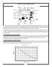
WATER SUPPLY CONNECTION: Ensure that you have read the
section entitled “PLUMBING THE DISHMACHINE” above before
proceeding. Install the water supply line (3/4” pipe size minimum)
to the dishmachine line strainer using copper pipe. It is recom-
mended that a water shut-off valve be installed in the water line
between the main supply and the machine to allow access for ser-
vice. The water supply line is to be capable of 20 PSI “flow” pres-
sure at the recommended temperature indicated on the data plate.
In areas where the water pressure fluctuates or is greater than the
recommended pressure, it is suggested that a water pressure reg-
ulator be installed.
Do not confuse static pressure with flow pressure. Static pressure
is the line pressure in a “no flow” condition (all valves and services
are closed). Flow pressure is the pressure in the fill line when the
fill valve is opened during the cycle.
It is also recommended that a shock absorber (not supplied with
the Tempstar-TGP model) be installed in the incoming water line.
This prevents line hammer (hydraulic shock), induced by the sole-
noid valve as it operates, from causing damage to the equipment.
PLUMBING CHECK: Slowly turn on the water supply to the
machine after the incoming fill line and the drain line have been
installed. Check for any leaks and repair as required. All leaks
must be repaired prior to placing the machine in operation.
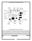
ELECTRICAL POWER CONNECTION: Electrical and grounding
connections must comply with the applicable portions of the
National Electrical Code ANSI/NFPA 70 (latest edition) and/or
other electrical codes.
Disconnect electrical power supply and place a tag at the discon-
nect switch to indicate that you are working on the circuit.
The dishmachine data plate is located on the right side and to the
front of the machine. Refer to the data plate for machine operat-
ing requirements, machine voltage, total amperage load and seri-
al number.
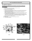
To install the incoming power lines, open the control box. This will
require taking a phillips head screwdriver and removing the one(1)
screw on the front cover of the control box. Install 3/4” conduit into
the pre-punched holes in the back of the control box. Route power
wires and connect to power block and grounding lug. Install the
service wires (L1 &L2) to the appropriate terminals as they are
marked on the terminal block. Install the grounding wire into the
lug provided. Tighten the connections and perform the “pull test”.
The tightened wires should remain in place after giving the wires
a moderate pull to see if they will come loose.
It is recommended that “DE-OX” or another similar anti-oxidation
agent be used on all power connections.
VOLTAGE CHECK: Ensure that the power switch is in the OFF
position and apply power to the dishmachine. Check the incoming
power at the terminal block and ensure it corresponds to the volt-
age listed on the data plate. If not, contact a qualified service
agency to examine the problem. Do not run the dishmachine if the
voltage is too high or too low. Shut off the service breaker and
mark it as being for the dishmachine. Advise all proper personnel
of any problems and of the location of the service breaker.
Replace the control box cover and tighten down the screws.
INSTALLATION INSTRUCTIONS
2